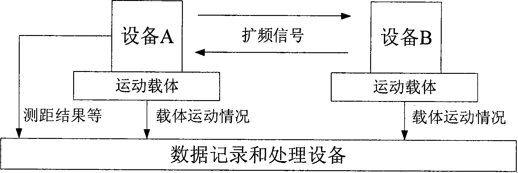
Bidirectional ranging and time comparision process terminal

A time comparison, two-way ranging technology, applied in the field of aerospace measurement and control communication, can solve the problems of low integration, inability to cancel time delay measurement errors, and inconvenient system design.

Inactive Publication Date: 2008-08-27
BEIHANG UNIV
View PDF0 Cites 39 Cited by
  • Summary
  • Abstract
  • Description
  • Claims
  • Application Information

AI Technical Summary

Problems solved by technology

[0015] (3) This method requires that the parameters such as the ranging code rate and modulation mode of the two links are consistent, otherwise the time synchronization between the two links is difficult to achieve
In a two-way measurement and control link with asymmetric data rate, this brings great inconvenience to the system design
[0016] (4) When the radio wave propagation medium is not uniform, or when the radio wave passes through the ionosphere, the radio wave propagation delay of the two links in this method changes in the same direction, and the delay measurement error caused by it cannot be canceled
[0017] 2. Traditional ranging accuracy error verification method
[0020] (1) Each device is independent of each other, the system is complex, and the integration level is low
[0021] (2) The verification accuracy of the ranging accuracy error is limited by the simulation accuracy of the actual carrier motion, or the signal delay simulation accuracy of the channel simulator, and the error verification accuracy is generally not high

Method used


Image

  • Bidirectional ranging and time comparision process terminal
  • Bidirectional ranging and time comparision process terminal
  • Bidirectional ranging and time comparision process terminal

Examples


Embodiment Construction

[0116] A two-way ranging and time comparison processing terminal of the present invention, according to design principles such as standardization, modularization, reliability and measurability, specifically includes (such as Figure 6 shown):

[0117] frequency reference;

[0118] RF front-end, including: noise source, frequency synthesis, transmit channel, receive channel;

[0119] Intermediate frequency signal processor;

[0120] Chassis;

[0121] display and control system; and

[0122] Power distributor.

[0123] The configuration of the entire processing terminal is a standard cabinet-fastened 4U chassis rear panel connector interconnection structure; the frequency reference, transmitting channel, receiving channel, intermediate frequency signal processor and power distribution are installed in the 4U chassis, and the display and control system is outside the planned configuration. It can be realized by setting notebook and display and control software, and interacti...


PUM


Abstract

The invention relates to a two-way ranging and time comparison processing terminal which is characterized in that: the processing terminal comprises a frequency benchmark, a radio frequency front end, a noise source, a frequency synthesis, a transmitting channel, a receiving channel, a medium frequency signal processor, a machine case, a display and control system, a power source distributor and a LAN switching module, wherein the configuration of the entire processing terminal is a 4U machine case postnotal plate joint interconnecting structure fastened by a standard machine cabinet; the frequency benchmark, the transmitting channel, the receiving channel, the medium frequency signal processor and the power source distributor are arranged inside a standard 4U machine case; the display and control system, which is realized through the configuration of an external notebook computer and display and control software, is in interaction with the outside through the LAN switching module. The entire processing terminal has simple equipment and high integration level; communication, ranging and time comparison are completed inside a unified channel, thereby saving frequency band resource; a pseudo code ranging system is adopted to ensure high ranging precision; moreover, the processing terminal, which has the functions of simulating dynamic state and time delay inside the transmitting channel, is used to realize the quantitative detection of the performance of a receiving terminal.

Description

(1) Technical field: [0001] The invention relates to a two-way ranging and time comparison processing terminal, which belongs to the technical field of aerospace measurement and control communication. (two) background technology: [0002] The core of the aerospace measurement and control communication system based on spread spectrum technology is to introduce digital communication technologies such as pseudo-code spread spectrum, pseudo-code ranging, and code division multiple access into the measurement and control system to realize satellite telemetry, remote control, ranging, speed measurement, Tracking, angle measurement, data transmission and other functions to complete measurement and control tasks, and realize multi-target measurement and control communication by code division multiple access. [0003] The principle of radio ranging is to measure the transmission delay of radio waves. First transmit radio waves, and then measure the time delay τ of the return signal ...

Claims


Application Information

Patent Timeline
Patent Type & Authority Applications(China)
IPC IPC(8): G01S5/02H04B1/38G01S19/01G01S19/13G01S19/35H04B1/40
Inventor 李雪徐勇常青刘磊张其善吴鑫山
Owner BEIHANG UNIV
Why Eureka
Try Eureka