
Method and apparatus rapidly regulating lidar transmit-receive system light path coaxial

A laser radar and transceiver system technology is applied in the field of rapidly adjusting the optical path coaxial of the laser radar transceiver system and the device, and can solve the problems of undiscovered, simple, easy and cost-effective laser radar optical device and method thereof.

Inactive Publication Date: 2008-08-27
ANHUI INST OF OPTICS & FINE MECHANICS - CHINESE ACAD OF SCI
View PDF0 Cites 15 Cited by
  • Summary
  • Abstract
  • Description
  • Claims
  • Application Information

AI Technical Summary

Problems solved by technology

We also investigated the materials of other laser research institutions, and found no easy-to-operate and low-cost optical device and method for fast alignment of the light-emitting path of the laser radar.

Method used


Image

  • Method and apparatus rapidly regulating lidar transmit-receive system light path coaxial
  • Method and apparatus rapidly regulating lidar transmit-receive system light path coaxial
  • Method and apparatus rapidly regulating lidar transmit-receive system light path coaxial

Examples


Embodiment Construction

[0081] The present invention will be further described below in conjunction with the embodiments and accompanying drawings, but the protection scope of the present invention should not be limited thereby.

[0082] 1. If Figure 7 As shown, the device of the present invention is inserted into the laser radar transmitting optical path, the initial receiving and receiving optical paths are not on the same axis, the angle between the receiving and receiving optical axes is δθ, and the distance is ΔD.

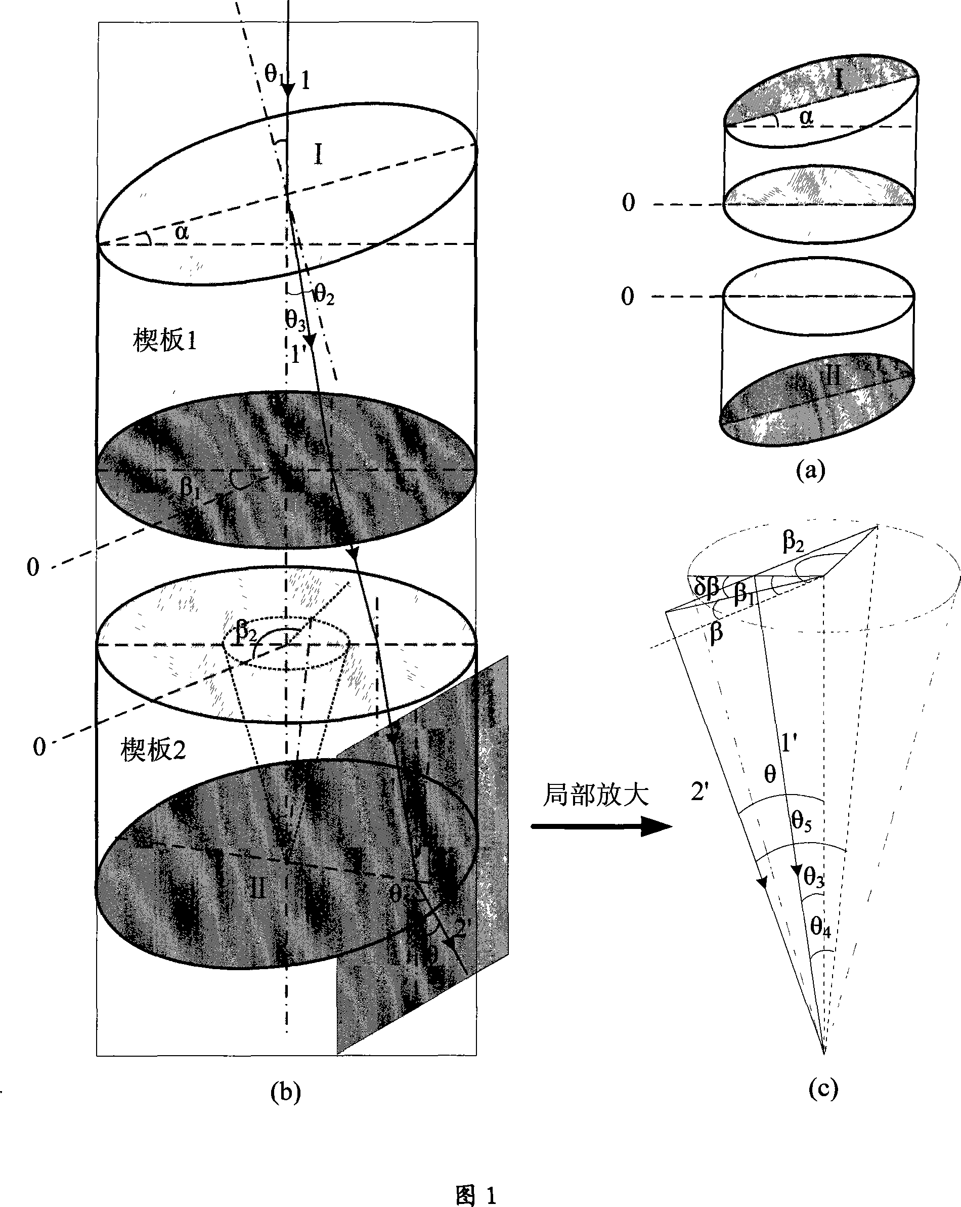
[0083] 2. ①The initial adjustment is controlled by the computer program to rotate the wedge-shaped optical plate 1 and wedge-shaped optical plate 2 (α=0.5°) by the stepping motor, so that the direction of the outgoing beam is roughly scanned along the helical line, and the pitch of the helical line is less than a certain fixed height r The receiving spot diameter at , that is, rΔθT +R L ), Δθ is the pitch; r is the distance corresponding to the processing signal during collimation, ...


PUM


Abstract

The invention discloses a method and a device capable of realizing fast coaxial adjustment of a lidar transceiver system light path. The device comprises a receiving telescope, a laser, a first wedge-shaped optic flat plate, a second wedge-shaped optic flat plate and a drive step motor thereof and a computer, etc. The two wedge-shaped optic flat plates are driven to rotate by the motor under the control of the computer, thereby ensuring that the direction of an emergent light beam changes continuously within a certain tapered space angular range. The method and the device can realize convenient and fast coaxial adjustment of the lasing beam of a lidar and a receiving telescope system.

Description

technical field [0001] The invention relates to an optical path coaxial calibration method and device for a laser radar system. Background technique [0002] Lidar is the product of the combination of traditional radar technology and modern laser technology. It uses laser as the source of electromagnetic radiation, uses laser echoes for distance measurement and orientation, and identifies objects through position, radial velocity, and emission characteristics of the target object. It embodies special emission, scanning, receiving, and signal processing technologies. An extremely important active remote sensing tool. There are many types of laser radars, which are divided according to their uses: shooting range laser radar, fire control laser radar, tracking and identification laser radar, multi-functional tactical laser radar, drug detection laser radar, navigation laser radar, meter scattering laser radar, Raman temperature measurement Water vapor lidar, Doppler wind meas...

Claims


Application Information

Patent Timeline
Patent Type & Authority Applications(China)
IPC IPC(8): G01S7/497G01S17/02G01C15/00
Inventor 孙东松沈法华李颖颖董晶晶岳斌舒志峰
Owner ANHUI INST OF OPTICS & FINE MECHANICS - CHINESE ACAD OF SCI
Learn More