Fusion splicing devices and methods of photon crystal optical fiber

A technology of photonic crystal fiber and fusion splicing, which is applied in the coupling of optical waveguide, program control in sequence/logic controller, electrical program control, etc. Distribution control, it is difficult to control the collapse degree of cladding air holes, etc., to achieve the effect of simple structure, strong anti-vibration interference ability, and avoid brittleness

Inactive Publication Date: 2008-08-27
YANSHAN UNIV
View PDF0 Cites 16 Cited by
  • Summary
  • Abstract
  • Description
  • Claims
  • Application Information

AI Technical Summary

Problems solved by technology

However, the photonic crystal fiber fusion splicing technology is still immature and still in the exploratory research stage, and has become a practical problem that must be solved in the application and development of photonic crystal fiber
[0003] Existing ordinary optical fiber fusion splicers and polarization-maintaining optical fiber fusion splicers cannot automatically complete the fusion splicing of photonic crystal fibers with high quality. The main problems are: 1. It is easy to cause the collapse of air holes in the cladding of photonic crystal fibers during fusion; 2. 1. Bubbles are easy to be generated when splicing large-aperture optical fibers; 3. Accurate control of splicing en

Method used


Image

  • Fusion splicing devices and methods of photon crystal optical fiber
  • Fusion splicing devices and methods of photon crystal optical fiber
  • Fusion splicing devices and methods of photon crystal optical fiber

Examples


Embodiment

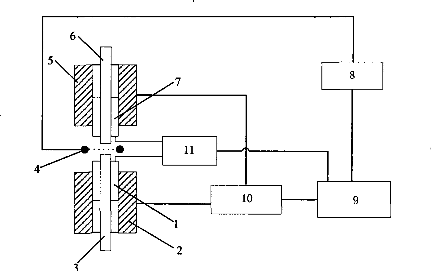
[0019] 1. The specifications of the fusion-spliced ​​lower and upper photonic crystal fibers (3, 6) are: the mode field radius is 7.5 μm, the core diameter is 10.9 μm, the hole spacing is 3 μm, the air hole diameter is 2 μm, and the number of air hole layers is 6 layers . Install the fused lower and upper photonic crystal fibers (3, 6) on the lower and upper three-dimensional motion V-groove devices (2, 5).

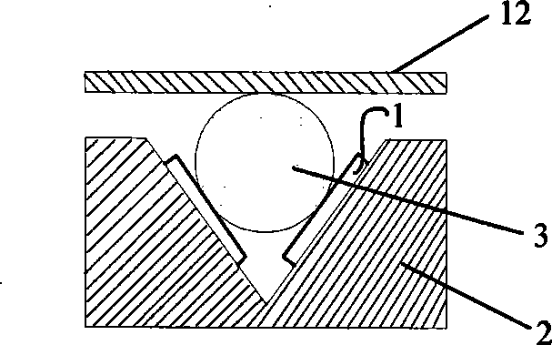
[0020] 2. According to the structural parameters of the lower and upper photonic crystal fibers (3, 6), pass through the lower and upper stress sensors (1, 7), the stress sensor demodulation unit 11, the three-dimensional alignment controller and the fixture control unit of the fixture control unit 10 The feedback control of the optical fiber clamp 12 automatically adjusts the clamping force of the lower and upper photonic crystal fibers (3, 6). The maximum pressure that this kind of photonic crystal fiber can withstand is 0.09N / μm. The clamping force used in the embodime...


PUM


Abstract

The invention discloses a welding device for photonic crystal fiber and a method thereof. A frequency controller (13) of a carbon dioxide laser modulating unit (8), a stress sensor demodulating unit (11) and a three-dimensional alignment controller and a clamp control unit (10) are connected with a processing and control element (9) of the welding device; mechanical transmission mechanisms of a lower three-dimensional motion V-shaped groove device (2) and an upper three-dimensional motion V-shaped groove device (5) are connected with the three-dimensional alignment controller and the three-dimensional alignment controller of the clamp control unit (10); the carbon dioxide laser modulating unit (8) transmits laser to a fiber output point (4) through a transmitting energy fiber (16) to weld a welded fiber (3). The method comprises the following steps of: 1) selecting a welding parameter according to information of a fiber structure; 2) adjusting a clamping force of the V-shaped groove clamp by using the information of the fiber structure; 3) performing a three-dimensional alignment to two fibers to be welded; 4) modulating a carbon dioxide laser by a frequency modulator with a set frequency to transmit laser to the position of welded fibers for welding through the transmitting energy fiber. The welding device for the photonic crystal fiber has the advantages of simple structure, strong capability of anti-interference of vibration, high sensitivity and easy manufacture, and is suitable for welding between photonic crystal fibers with different specifications and between the photonic crystal fiber and a conventional optical fiber.

Description

technical field [0001] The invention relates to the technical field of photonic crystal fiber fusion, in particular to a photonic crystal fiber fusion splicing device and method thereof. Background technique [0002] Photonic crystal fiber came out in the UK in 1996. This kind of fiber has many singular characteristics that ordinary fibers do not have, such as high nonlinearity, controllable dispersion, high birefringence, infinite single-mode characteristics, etc., and can be widely used in In the fields of communication, imaging, spectroscopy and biomedicine, its performance research and application development have always been a hot spot in the international optoelectronics industry. However, the photonic crystal fiber fusion splicing technology is still immature and still in the exploratory research stage, and has become a practical problem that must be solved in the application and development of photonic crystal fiber. [0003] Existing ordinary optical fiber fusion s...

Claims


Application Information

Patent Timeline
IPC IPC(8): G02B6/255G05B19/04
Inventor 毕卫红付广伟刘强
Owner YANSHAN UNIV
Why Eureka
Try Eureka