Front end combination purification technique for producing liquefied natural gas from mixture gas rich-containing methane

A technology of liquefied natural gas and mixed gas, which is applied in the fields of gas fuel, petroleum industry, fuel, etc., can solve the problems of the production capacity decline of the liquefaction plant, the excessive acid gas components, and the reduction of the gas liquefaction rate, so as to reduce the energy consumption of regeneration and improve the production capacity. The effect of high rate and removal rate

Active Publication Date: 2008-09-10
成都五环新锐化工有限公司
View PDF0 Cites 36 Cited by
  • Summary
  • Abstract
  • Description
  • Claims
  • Application Information

AI Technical Summary

Problems solved by technology

The specific performance is as follows: ① Existing devices usually use the MEA solution process to remove acid gases (CO2, H2S, HCN). Due to the instability of the solution system, especially when the mixed gas contains organic sulfur, the solution is prone to irreversible degradation, often As a result, the acid gas components in the gas after the purification of the amine system exceeded the standard; ②The existing devices all adopt a single-stage temperature and pressure swing adsorption process for dehydration and removal of high-carbon hydrocarbons. It is regeneration gas, and the amount of regeneration gas is very large, accounting for about 25% to 60% of the process gas, which reduces the liquefaction rate of the gas; second: moisture and heavy hydrocarbons are removed on the same adsorbent, resulting in partial load of drying and purification Large, forcing the system to reduce the load operation, reducing the production capacity of the entire liquefaction unit

Method used


Image

  • Front end combination purification technique for producing liquefied natural gas from mixture gas rich-containing methane
  • Front end combination purification technique for producing liquefied natural gas from mixture gas rich-containing methane
  • Front end combination purification technique for producing liquefied natural gas from mixture gas rich-containing methane

Examples


Embodiment 1

[0090] Pipeline natural gas to produce liquefied natural gas (LNG)

[0091] 1. Raw material conditions

[0092] composition

[0093]

[0094] Flow rate: 10000Nm3 / h

[0095]Pressure: 2.5Mpa.G~3.5Mpa.G

[0096] 2. Purification requirements

[0097] Water content ≤1ppm

[0098] Benzene content ≤10ppm

[0099] CO2≤20ppm

[0100] ∑S ≤1ppm

[0101] Atmospheric dew point ≤-70℃

[0102] 3. Brief description of the process

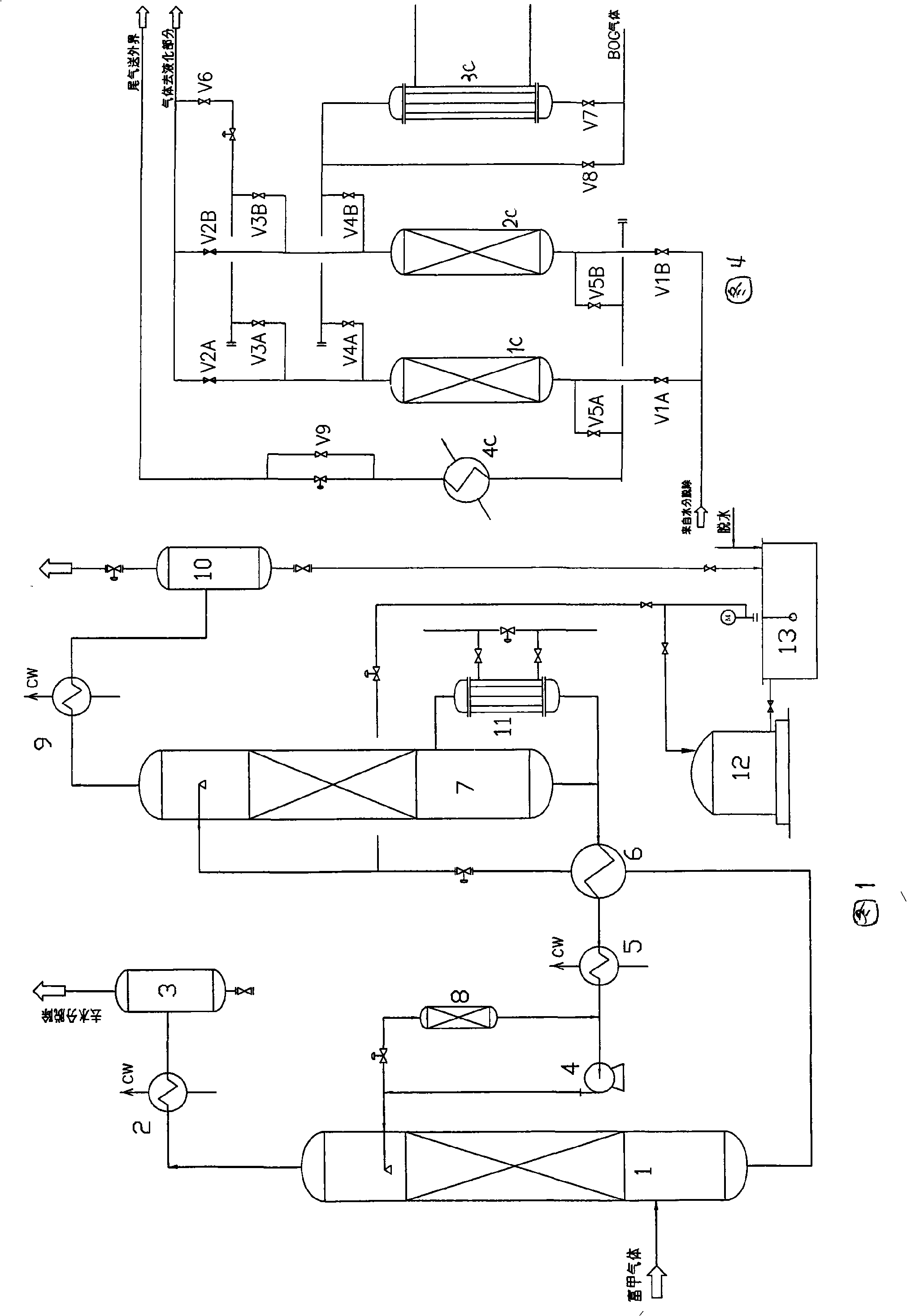
[0103] Figure 6 shows that natural gas is introduced from the outside world and first enters the complex amine absorption system. Due to the low content of acid gas in the raw gas and the small amount of solution circulation, the two-stage absorption / two-stage regeneration process is adopted, which has limited energy saving and complicates the process. Therefore, a one-stage absorption / one-stage regeneration process is adopted. The CO2 in the natural gas purified by the complex amine absorption system is ≤20ppm, and enters the isobaric regeneration dehy...


PUM


Abstract

The invention discloses a front-end combined purification process used to produce liquefied natural gas from mixed gas richly containing methane, which comprises four unit parts: acid gas removal, drying and dehydration, heavy hydrocarbon removal and demercuration. The mixed gas firstly undergoes a purification treatment through composite amine solution, CO2, H2S and HCN acid gases in the mixed gas are removed to the concentration less than or equal to 20ppm; the moisture in the gas is removed to a dew point at normal pressure less than or equal to minus 70 DEG C through isopiestic drying and dehydration treatment, then heavy hydrocarbon components above C5 are removed to the concentration less than or equal to 10ppm through temperature-changing pressure-changing absorption and purification treatment; finally the mercury content is removed to the value less than or equal to 0.001mu g/Nm<3> through the demercuration of demercuration adsorbent. The process has better purification effect than the conventional process route, improves the utilization rate of the raw materials and decreases the energy consumption during the purification; and the operation indexes of the units are easier to control.

Description

technical field [0001] The invention belongs to the front-end purification treatment technology of methane-rich gas low-temperature liquefaction. Specifically, for an industrial device that obtains liquefied natural gas (LNG) from a mixed gas rich in methane, it is necessary to remove the acid gas components, water, and high-carbon hydrocarbons contained therein before the mixed gas is subjected to cryogenic liquefaction. The precision required for liquefaction is the only way to ensure the safe and stable operation of the liquefaction separation process and equipment. Background technique [0002] Under the pressure of environmental protection and energy costs, the proportion of natural gas as a primary energy source in various fields of society is gradually increasing, and its market demand is also increasing rapidly. The traditional pipeline transportation supply method is still the mainstream, but due to the limitation of raw material conditions and user distribution, a...

Claims


Application Information

Patent Timeline
Patent Type & Authority Applications(China)
IPC IPC(8): C10L3/08
Inventor 黄吉荣王浩
Owner 成都五环新锐化工有限公司
Why Eureka
Try Eureka