Composite binding course material and method for producing composite binding course by using combination of plating and electro beam physics vapour deposition

A technology of physical vapor deposition and bonding layer, which is applied in the direction of metal material coating technology, superimposed layer plating, chemical instruments and methods, etc., can solve the problem of reducing the mechanical properties of ultra-high temperature alloy substrates, the decline of creep resistance, and the harmful TCP equal problem, to achieve excellent high-temperature oxidation resistance and avoid the decline of high-temperature mechanical properties

Inactive Publication Date: 2008-09-24
BEIHANG UNIV
View PDF0 Cites 11 Cited by
  • Summary
  • Abstract
  • Description
  • Claims
  • Application Information

AI Technical Summary

Problems solved by technology
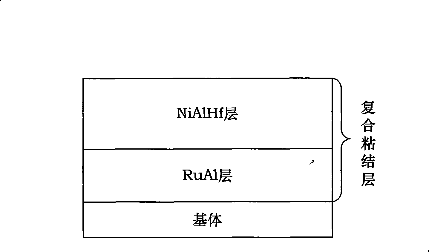
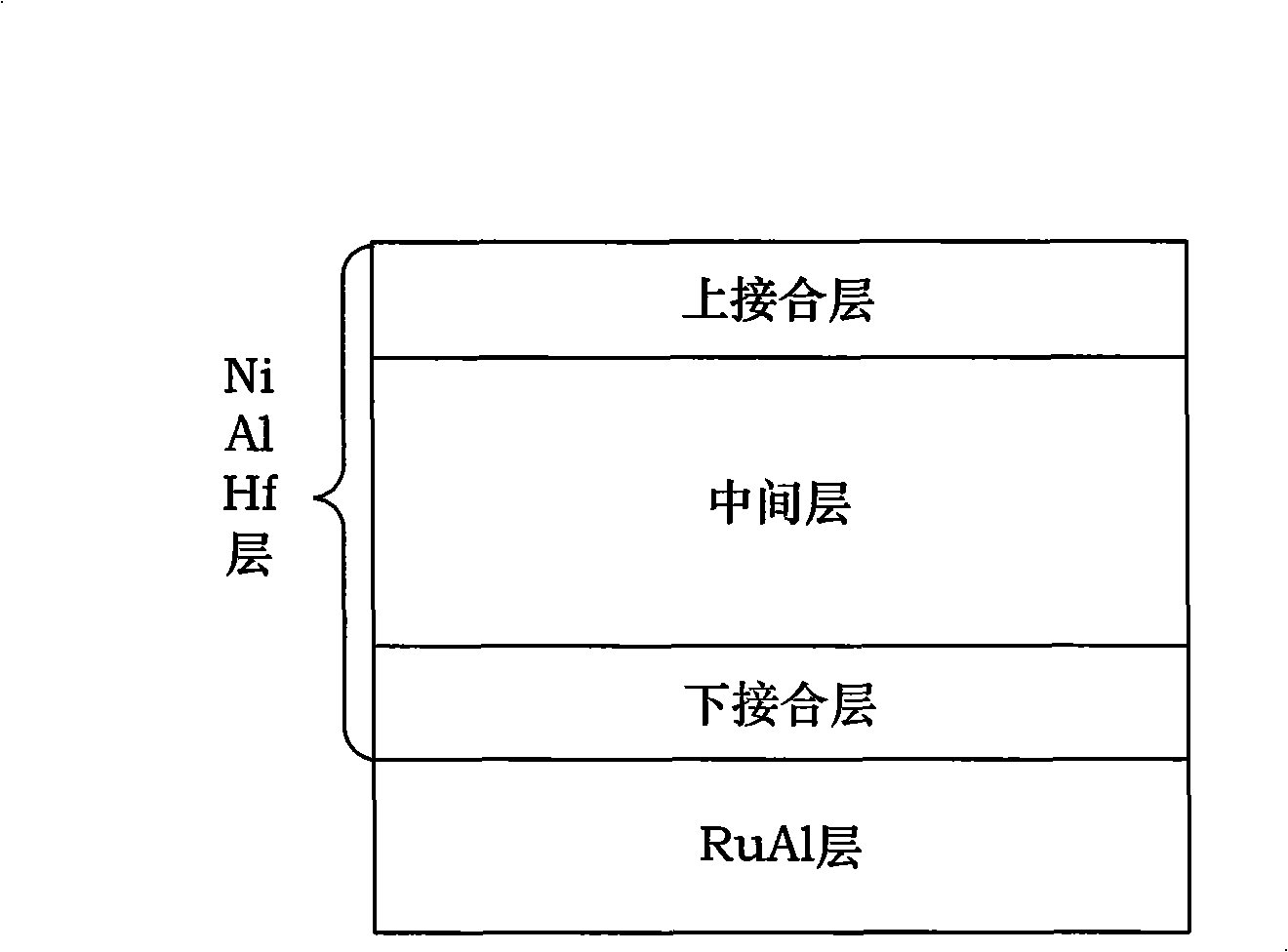
Especially for the new generation of single crystal superalloys containing Re and Ru, its Re and Ru will diffuse outward from the substrate, and Al will diffuse from the bonding layer into the substrate to form a second reaction zone (SRZ). Both seriously reduce the mechanical properties of the ultra-high temperature alloy matrix, especially the creep resistance is greatly reduced
In addition, due to interdiffusion of elements, harmful TCP phase
[0004] Traditional bonding layer materials usually use MCrAlY alloys (M is generally Ni, Co or Ni+Co), which can only be used in environments below 1150 °C

Method used


Image

  • Composite binding course material and method for producing composite binding course by using combination of plating and electro beam physics vapour deposition
  • Composite binding course material and method for producing composite binding course by using combination of plating and electro beam physics vapour deposition
  • Composite binding course material and method for producing composite binding course by using combination of plating and electro beam physics vapour deposition

Examples


Embodiment 1

[0112] The first step, substrate pretreatment

[0113] (A) The substrate is a Ni-based superalloy, the grade is K3, and the size is 8mm×9mm×3mm; each surface of the substrate is polished with 150#, 400#, and 800# SiC water abrasive paper to make the surface roughness of the substrate Ra <0.8;

[0114] (B) putting the substrate treated in step (A) into an alkaline cleaning solution at 60° C. for 5 minutes, and then rinsing it with deionized water for 3 times to obtain the first substrate;

[0115] The alkaline cleaning solution is composed of NaOH, Na 2 CO 3 、Na 3 PO 4 and deionized water, add 15g of NaOH and 15g of NaOH to 1L of deionized water 2 CO 3 and 15g of Na 3 PO 4 ;

[0116] (C) putting the first substrate obtained through the treatment in step (B) into 5% HCl for activation for 40 seconds, and then rinsing it twice with deionized water to obtain the second substrate;

[0117] The second step, electroplating the Ru layer

[0118] After the second substrate o...

Embodiment 2

[0163] The first step, substrate pretreatment

[0164] (A) The substrate is a Ni-based superalloy containing 4wt% Ru of the brand UM-F3, and the size is 9mm×9mm×3mm; each surface of the substrate is polished with SiC water abrasive paper of 150#, 400#, and 800# respectively, Make the substrate surface roughness Ra<0.8;

[0165] (B) putting the substrate treated in step (A) into an alkaline cleaning solution at 70° C. for 2 minutes, and then rinsing it twice with deionized water to obtain the first substrate;

[0166] The alkaline cleaning solution is composed of NaOH, Na 2 CO 3 、Na 3 PO 4and deionized water, add 30g of NaOH and 30g of NaOH to 1L of deionized water 2 CO 3 and 30g of Na 3 PO 4 ;

[0167] (C) putting the first substrate obtained through the treatment in step (B) into 5% HCl for activation for 60 seconds, and then rinsing it with deionized water for 3 times to obtain the second substrate;

[0168] The second step, electroplating the Ru layer

[0169] Af...

Embodiment 3

[0213] The first step, substrate pretreatment

[0214] (A) The substrate is a Ni-based single crystal alloy containing 2wt% Re, the grade is DD6, and the size is 8mm×9mm×3mm; each surface of the substrate is polished with SiC water abrasive paper of 150#, 400#, and 800# respectively, Make the substrate surface roughness Ra<0.8;

[0215] (B) putting the substrate treated in step (A) into an alkaline cleaning solution at 65° C. for 3 minutes, and then rinsing it with deionized water for 3 times to obtain the first substrate;

[0216] The alkaline cleaning solution is composed of NaOH, Na 2 CO 3 、Na 3 PO 4 and deionized water, add 10g of NaOH and 10g of NaOH to 1L of deionized water 2 CO 3 and 10 g of Na 3 PO 4 ;

[0217] (C) putting the first matrix obtained through the treatment in step (B) into 5% HCl for 20 seconds of activation, and then rinsing it twice with deionized water to obtain the second matrix;

[0218] The second step, electroplating the Ru layer

[0219...


PUM

PropertyMeasurementUnit
melting pointaaaaaaaaaa
densityaaaaaaaaaa

Abstract

The invention discloses a composite bonding layer material and a method thereof to combine and prepare a composite bonding layer by adopting electroplating and electron beam physical gas-phase deposition, the composite bonding layer manufactured by the combining method has fore layers of structures, the composite bonding layer consists of a RuA1 layer and a NiA1Hf layer; the A1 content in the RuA1 layer is 30 to 50 percent, the residual is Ru; the NiA1Hf layer consists of a lower connecting layer, a middle layer, and an upper connecting layer; the A1 content in the lower connecting layer is 70 to 90 percent, the Hf content is 0.5 to 3 percent, the residual is Ni; the A1 content in the middle layer is continuously reduced from 70 to 90 percent to 40 to 50 percent, the Hf content is 0.5 to 3 percent, the residual is Ni; the A1 content in the upper connecting layer is 40 to 50 percent, the Hf content is 0.5 to 3 percent, and the residual is Ni.

Description

technical field [0001] The invention relates to a method for preparing a bonding layer in a thermal barrier coating, more particularly, a method for preparing a diffusion-resistant coating with a double-layer structure of RuAl and NiAlHf by combining electroplating and electron beam physical vapor deposition. Method of making the bonding layer. Background technique [0002] The development of advanced gas turbine engines requires turbine blades and guide vanes to work at temperatures between 1500°C and 1600°C for a long time. In order to adapt to this harsh working environment and meet the development needs of aero-engines, thermal barrier coatings (Thermal Barrier Coatings), as a surface thermal protection technology, were developed in the 1960s. [0003] The thermal barrier coating structure is mainly composed of a ceramic layer and an adhesive layer (see Figure 5 shown), the bonding layer is located between the substrate and the ceramic layer. The ceramic layer is used...

Claims


Application Information

Patent Timeline
Patent Type & Authority Applications(China)
IPC IPC(8): B32B15/01B32B5/14C22C21/00C22C5/00C23C28/02C25D3/50C23C14/16C23C14/30C23C14/54C23G1/20
Inventor 宫声凯王莹郭洪波徐惠彬
Owner BEIHANG UNIV
Why Eureka
Try Eureka