Diffraction optics element scan etching device with etch deepness on-line detection mechanism

A diffractive optical element and detection mechanism technology, applied in the field of science, can solve problems such as inability to realize online detection of etching depth

Inactive Publication Date: 2011-01-26
UNIV OF SCI & TECH OF CHINA
View PDF0 Cites 0 Cited by
  • Summary
  • Abstract
  • Description
  • Claims
  • Application Information

AI Technical Summary

Problems solved by technology

[0006] In order to solve the problem that the existing scanning ion beam etching device cannot realize the online detection of etching depth, the present invention provides a scanning etching device for diffractive optical elements with an online detection mechanism for etching depth

Method used


Image

  • Diffraction optics element scan etching device with etch deepness on-line detection mechanism
  • Diffraction optics element scan etching device with etch deepness on-line detection mechanism
  • Diffraction optics element scan etching device with etch deepness on-line detection mechanism

Examples


Embodiment 1

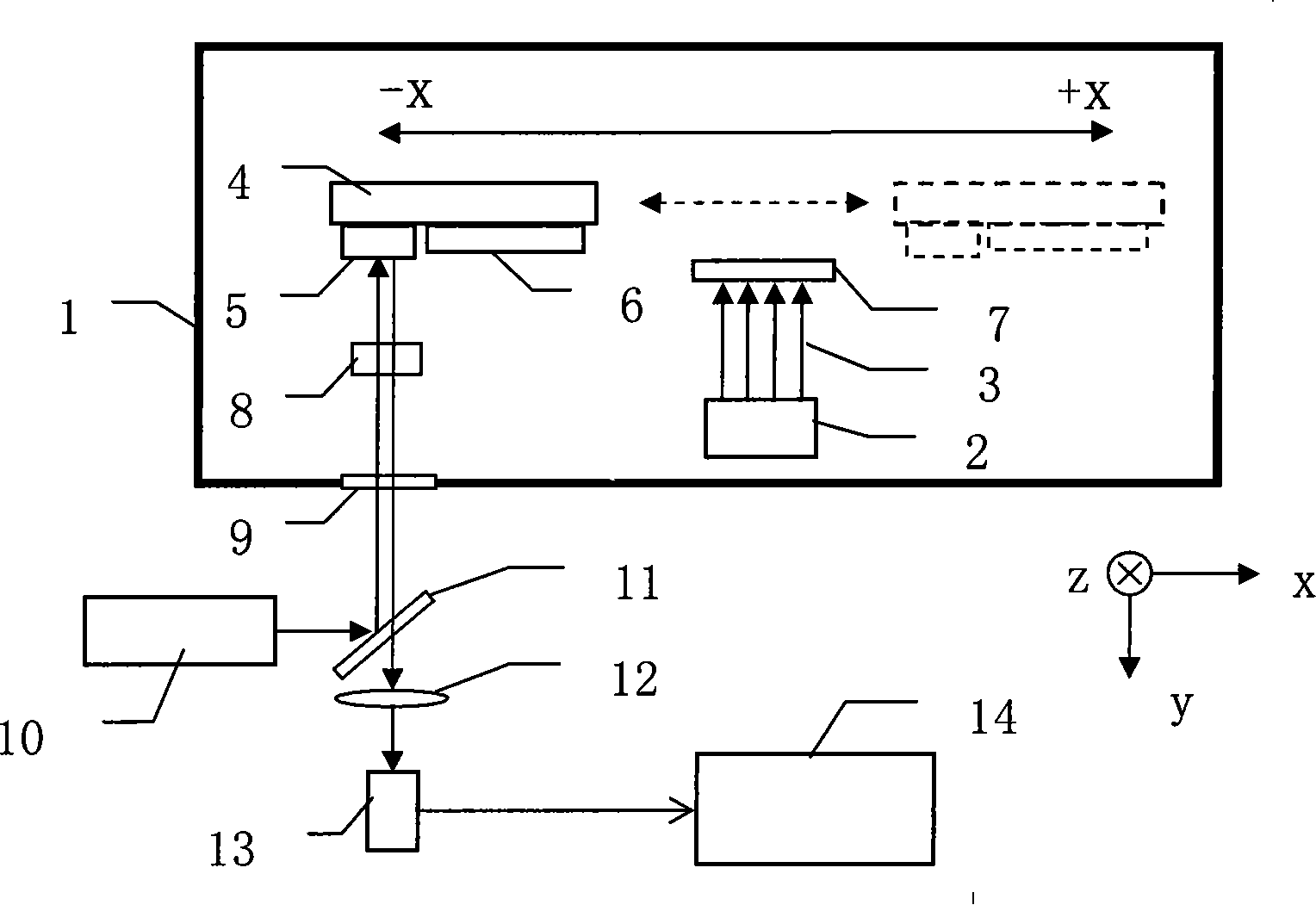
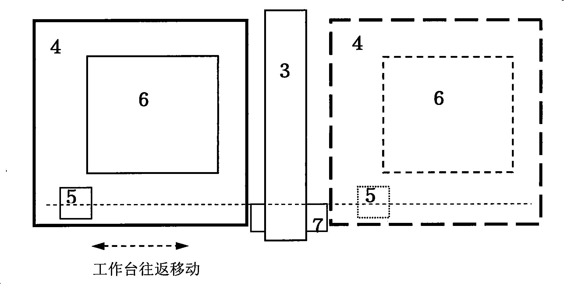
[0049] see Figure 1 and figure 2, The diffractive optical element scanning etching device with an etching depth on-line detection mechanism includes a vacuum chamber 1 with an observation window, an ion source 2, an ion beam stop 3, and a translation table 4, and the work table of the translation table 4 is to be etched. The optical element 6, the translation workbench 4 can translate along the +x and -x directions, the incident direction of the ion beam is perpendicular to the work surface of the workbench, that is, the direction of the ion beam emitted by the ion source is approximately parallel to the normal line of the workbench, Its observation window 9 is basically parallel to the normal direction of the working surface of the translation workbench. The accompanying sheet 5 and the optical element (formal substrate) 6 to be etched are fixed on the working surface of the workbench, and the graphite baffle 7 is fixed at a suitable position on the ion beam stop to block ...

Embodiment 2

[0060] The structure of the diffractive optical element scanning etching device with an etching depth on-line detection mechanism is the same as in Embodiment 1, wherein the material of the optical element 6 to be etched is fused silica, and a phase-type Ronchi grating with a target etching depth of 690±15 nm.

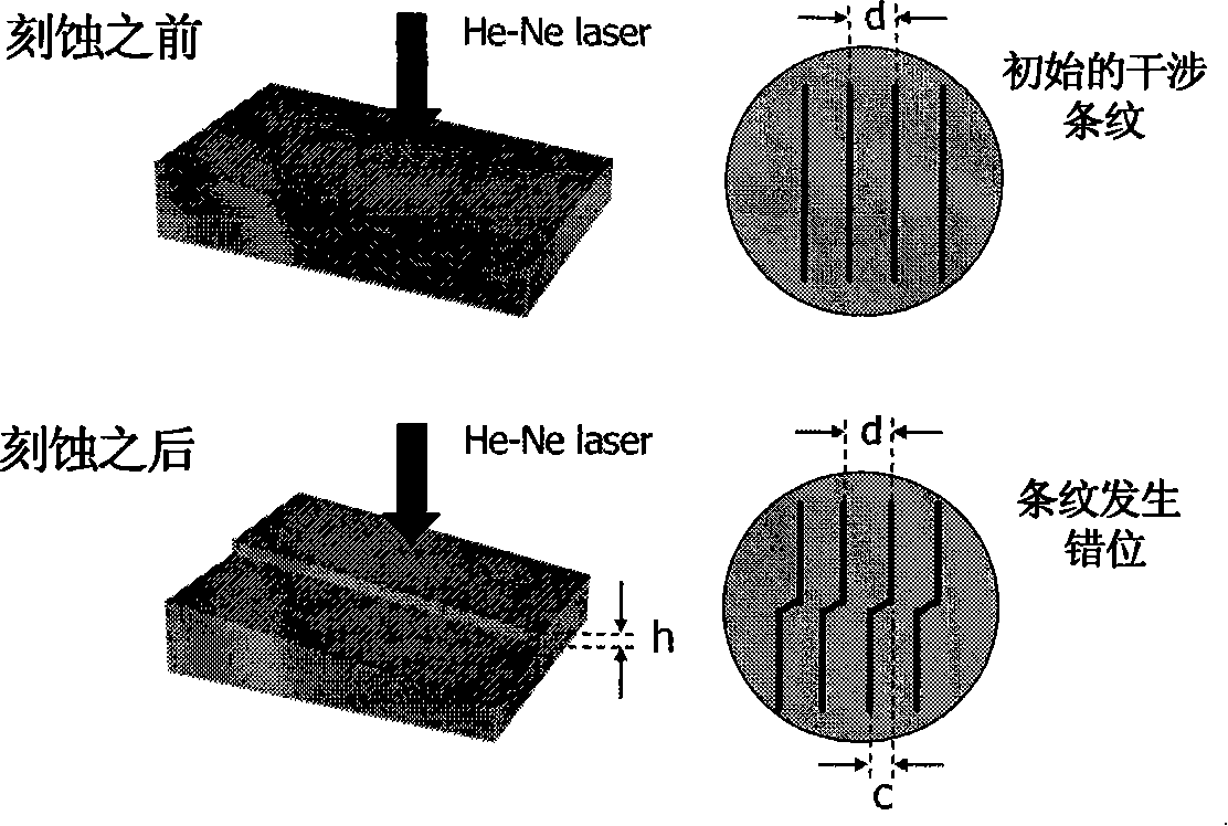
[0061] The accompanying sheet 5 used in the detection is the same as that used in Example 1, which is a circular sheet with a diameter of 25mm and a thickness of about 3mm, and the material is fused silica; the linear density of its equal-thickness stripes is about 10 lines / cm; The etching depth corresponding to the fringe interval is about 217 nanometers, so when the dislocation ratio of equal-thickness fringes of the companion sheet reaches about 3.180 ((690±15) / 217≈3.180±0.069), the etching should be stopped.


PUM


Abstract

The present invention relates to a diffraction optical element scanning etching device which is provided with an etching depth on-line detecting mechanism. The invention settles the problem that the existing device can not realize the etching depth on-line detection. Through the improvement to the original scanning type ion beam etching device, the side of a parallel-moving worktable in the vacuum chamber is provided with an accompanying piece. The ion beam lace is provided with a graphite repelling board. A pair of optical surface reflectors is provided between the parallel-moving worktable and an observing window. The outside of the vacuum chamber is provided with a beam splitter, a convex lens, a planar array cam and a computer. The side of the light splitter is provided with a laser source. The invention can effectively realize the on-line measurement of etching depth in the scanning type ion beam etching process of the diffraction optical element. The etching time of the ion beamcan be on-line and dynamically regulated. The etching depth of the theoretical design accurately obtained in one time. The etching depth can be measured according to the invention is from about 50 or60 nanometers to about 700 nanometers and basically covers the dimension range of ''submicron''.

Description

technical field [0001] The invention relates to the fields of science and technology such as diffractive optics and microfabrication, and in particular to a scanning ion beam etching device used for processing and manufacturing diffractive optical elements and having the function of on-line detection of etching depth. Background technique [0002] The ion beam etching process plays an important role in the fabrication of diffractive optical elements, binary optical elements and other microstructures. In the early ion beam etching process, the etching depth of the material was controlled by setting the etching time in advance. The prerequisite for this to work is that the etch rate of the material is approximately equal in each etch pass. However, since the ion beam etching process is very complicated, many uncertain factors will affect the etching characteristics of the material, so that the actual etching rate will not always be very stable. If the etching depth is simply...

Claims


Application Information

Patent Timeline
Patent Type & Authority Patents(China)
IPC IPC(8): G02B5/18
Inventor 徐作冬刘颖徐向东徐德权洪义麟付绍军
Owner UNIV OF SCI & TECH OF CHINA
Why Eureka
Try Eureka