
Method for absorbing CO2 of stack gas by ammonia water

A flue gas and CO2 technology, applied in separation methods, chemical instruments and methods, air quality improvement, etc., can solve the problems of secondary pollution, large amount of ammonia, small gas resistance drop and removal efficiency, etc., to reduce carbon dioxide Effect

Inactive Publication Date: 2008-11-05
北京卓易天元科技发展有限公司 +1
View PDF1 Cites 15 Cited by
  • Summary
  • Abstract
  • Description
  • Claims
  • Application Information

AI Technical Summary

Problems solved by technology

Chinese patent CN1833756A proposes to absorb carbon dioxide with ammonia water using a supergravity field. The gas resistance drop of this method is small and the removal efficiency is high, but it is not suitable for the treatment of flue gas in large-scale power generation equipment
Due to the large flue gas flow rate of power plant boilers and the consideration of energy consumption, normal pressure absorption is generally used, and ammonia water is used to absorb flue gas in the first stage, so that the amount of ammonia taken away with flue gas is relatively large, causing secondary pollution and increasing costs; Even if a cleaning tower is added after the absorption tower, due to the water balance requirements of the system, it is often necessary to concentrate and circulate dilute ammonia water, and it is difficult to avoid this problem

Method used


Image

  • Method for absorbing CO2 of stack gas by ammonia water
  • Method for absorbing CO2 of stack gas by ammonia water

Examples


Embodiment 1

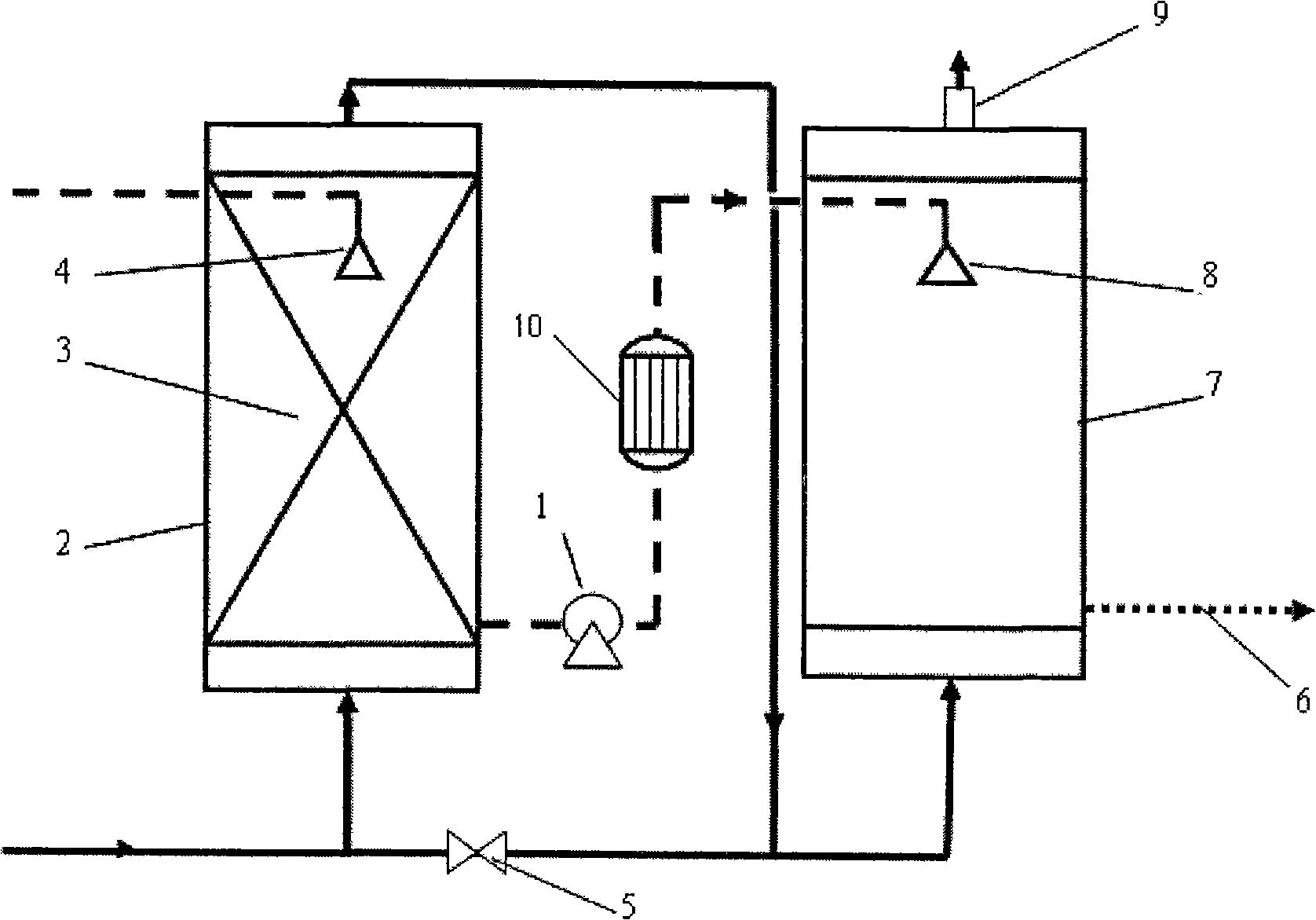
[0044] as attached figure 1 , a method of absorbing CO2 in flue gas with ammonia water:

[0045] ① will be used by industry O 2 , N 2 , CO 2 According to the flue gas composition of the power plant, 3% O in the volume ratio of each component 2 , 84% N 2 , 13% CO 2 The mixed flue gas is first pressurized to 0.4-0.6 MPa by a gas compressor, and then sent to the primary ammonia water spray tower 2 from the bottom. According to the absorption effect, part of the flue gas directly enters the secondary ammonium carbonate spray tower 7 by opening the intake control valve 5 .

[0046] ②Ammonia water with a concentration of 15% is sprayed from the top of the primary ammonia water spray tower 2 through the ammonia water sprayer 4, so that the ammonia water sprayed above and the flue gas are fully contacted to make the gas-liquid two-phase contact reaction.

[0047] ③ Control the reaction temperature in the primary ammonia water spray tower 2 to 35°C, and the reaction products are a...

Embodiment 2

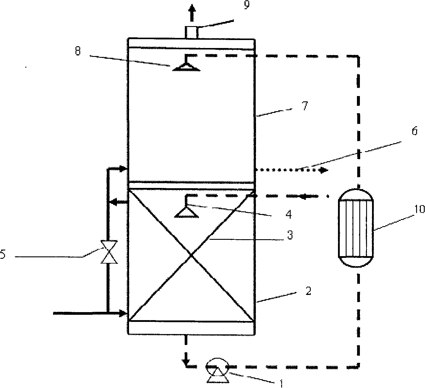
[0052] as attached figure 2 , a process for removing high-concentration carbon dioxide in flue gas:

[0053] ① will be used by industry O 2 , N 2 , CO 2 Prepare the simulated flue gas with the content of each component as follows: 3% O 2 , 47% N 2 , 50% CO 2 . The simulated flue gas is fed into the primary ammonia spray tower 2 from the bottom through the intake device. According to the absorption effect, part of the flue gas directly enters the secondary ammonium carbonate spray tower 7 by opening the intake control valve 5 .

[0054] ② Spray ammonia water with a concentration of 15.0% from the top of the first-stage spray tower 2 through the ammonia water sprayer 4 to make the gas-liquid two-phase contact reaction, so that the flue gas fully contacts with the ammonia water sprayed above.

[0055] ③ Control the reaction temperature in the primary ammonia water spray tower 2 to 35° C., and the reaction products are ammonium carbonate and ammonium carbamate solutions. ...


PUM


Abstract

The invention relates to a method for generating ammonium bicarbonate by using ammonia water to absorb carbon dioxide in flue gas. The method divides a spray tower into two stages. Flue gas in the first stage of the spray tower contacts 6 to 18 percent of ammonia water in a converse manner to generate ammonium carbamate or ammonium carbamate and ammonium carbonate; in the second stage of the spray tower, the flue gas contacts absorption liquid coming from the bottom of the first stage of the spray tower and containing ammonium carbamate and ammonium carbonate in a converse manner to further generate ammonium bicarbonate. At last, the gas is discharged from the top of the tower. The method has the advantages of greatly reducing the content of ammonia in the flue gas from which CO2 is removed, secondary pollution as well as operation cost.

Description

technical field [0001] The invention relates to a process for generating ammonium bicarbonate by removing carbon dioxide in the flue gas of a power plant with ammonia water. Background technique [0002] Carbon dioxide is the main component of greenhouse gases, and the burning of fossil fuels is the largest source of atmospheric environmental pollution and a huge source of CO 2 Greenhouse gas release source, and global warming will bring unprecedented disasters to human beings. Therefore, it is urgent to remove carbon dioxide in the boiler flue gas of coal-fired power plants. [0003] The control of the greenhouse gas carbon dioxide has received worldwide attention. At present, the technologies used in industry include: physical absorption method, chemical absorption method, physical adsorption method, membrane separation method, low-temperature fractionation method, biological method, etc., and many of the above methods are summarized into two categories: one is to change ...

Claims


Application Information

Patent Timeline
IPC IPC(8): B01D53/62B01D53/78
CPCY02C10/04Y02A50/20Y02C20/40
Inventor 胡永琪向哲愚杨晓东刘润静赵风云邸丹刘世瑞
Owner 北京卓易天元科技发展有限公司
Learn More