Melting strip electrode automatic condensed electric arc re-melt deposit welding method and device thereof

A melting zone and arc technology, applied in arc welding equipment, welding equipment, welding accessories, etc., can solve the problems of unstable bonding strength and performance, slag inclusion at the bonding interface, and inability to guarantee welding rate, etc., achieving low cost, The effect of high deposition welding strength and stable welding quality

Active Publication Date: 2008-11-12
NANJING UNIV OF SCI & TECH
View PDF0 Cites 7 Cited by
  • Summary
  • Abstract
  • Description
  • Claims
  • Application Information

AI Technical Summary

Problems solved by technology
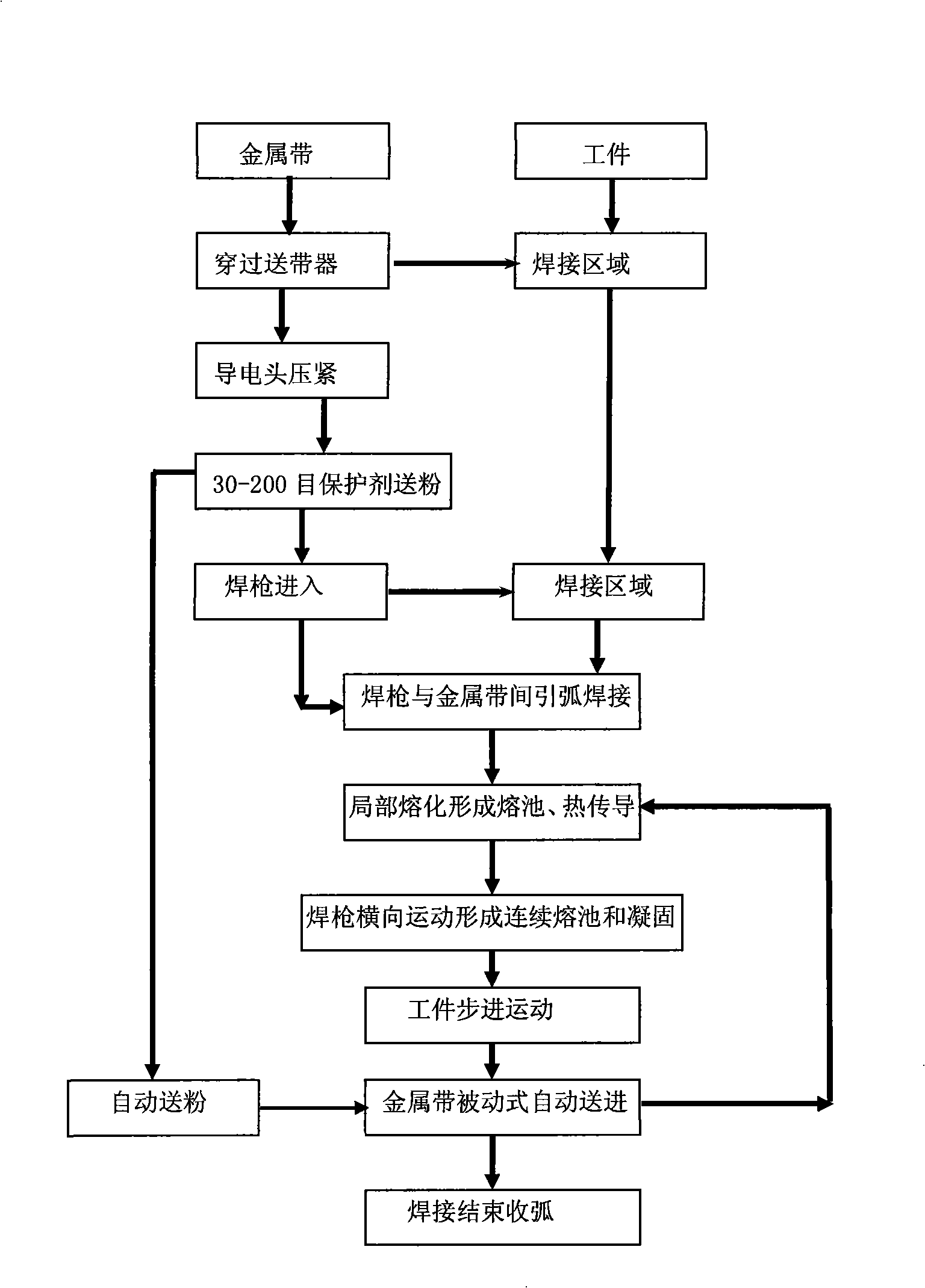
The heating time is a few seconds, there is a certain welding area, but the welding rate cannot be guaranteed to reach 1

Method used


Image

  • Melting strip electrode automatic condensed electric arc re-melt deposit welding method and device thereof
  • Melting strip electrode automatic condensed electric arc re-melt deposit welding method and device thereof
  • Melting strip electrode automatic condensed electric arc re-melt deposit welding method and device thereof

Examples


Embodiment 1

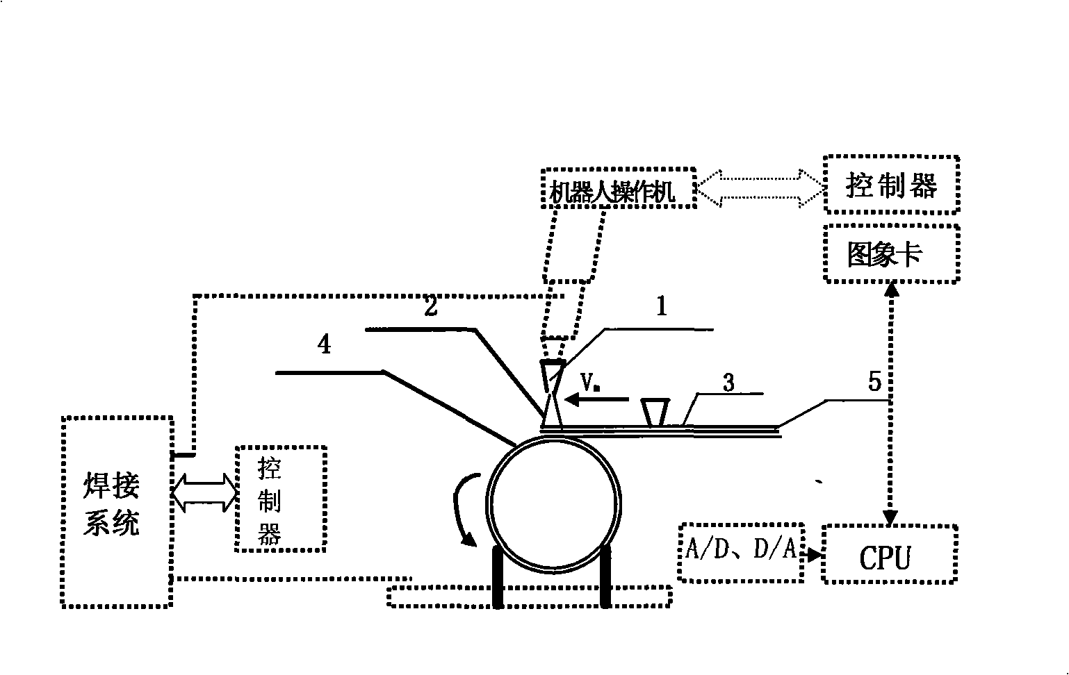
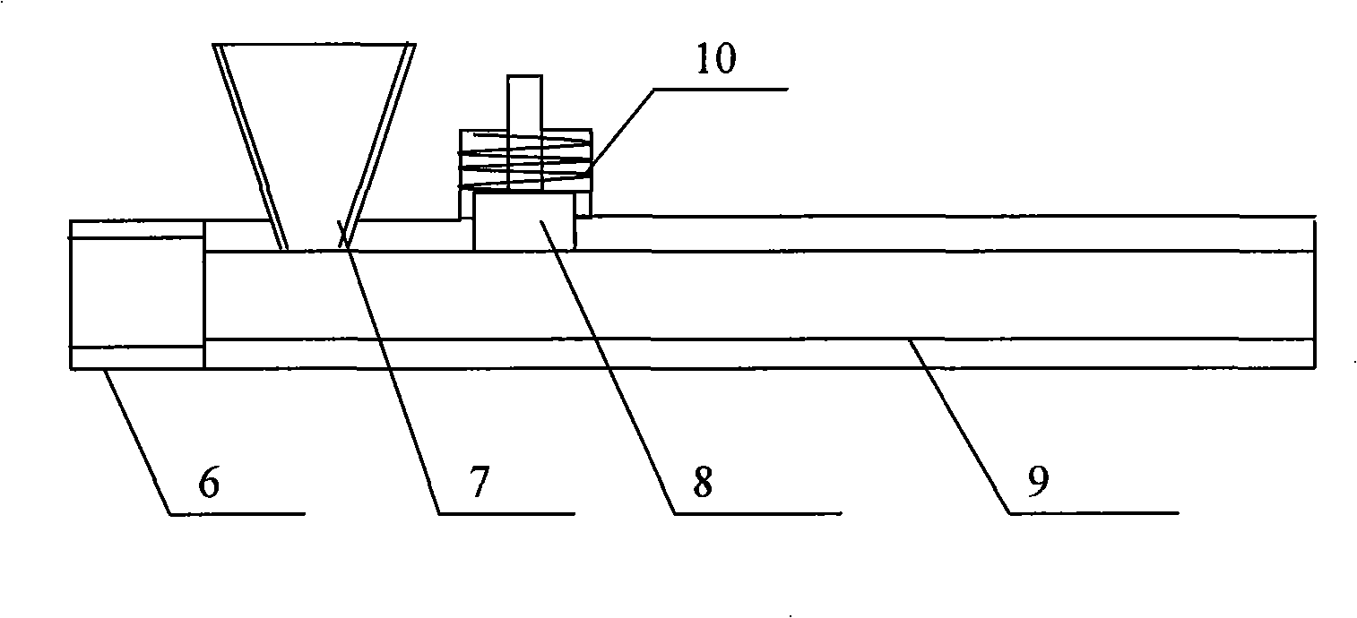
[0022] Example 1: Combining Figures 1 to 3, taking the 155mm diameter 58SiMn cylindrical body (cylinder) surface welding brass layer as an example. Pass the 5cm×5mm96 brass metal strip through the specially designed rectangular strip feeding tube 9 of the strip feeder 3 to the surface of the tubular (155mm outer diameter) steel substrate to be welded. The inner hole of the rectangular strip feeding tube 9 is 55mm wide and 6mm high , there is a protective agent automatic filling device powder feeder 7 (filling funnel) above the rectangular feeding pipe 9, the size of the leak hole at the bottom of the funnel is 20-35mm×20-30mm, the protective agent mesh is 60-120 mesh, and the rectangular feeding pipe 9. The 1mm difference between the thickness of the inner rectangular hole and the thickness of the brass metal strip determines the amount of protective agent delivered. With the automatic feeding of the brass metal strip, the protective agent is evenly and automatically spread o...

Embodiment 2

[0023] Example 2: Combining Figures 1 to 3 , taking the stainless steel layer deposited on the surface of a 170mm diameter 45 cylindrical body (cylinder) as an example. Pass the 4cm×4mm 1Cr18Ni9Ti stainless steel strip through the specially designed rectangular strip feeding tube 9 of the strip feeder to the part to be welded on the surface of the tubular (170mm outer diameter) steel substrate. There is a protective agent automatic filling device powder feeder 7 (filling funnel) above the rectangular tape feeding pipe 9, the size of the hole at the bottom of the funnel is 20-30mm×20-25mm, the mesh number of the protective agent is 40-80 mesh, and the rectangular tape feeding pipe 9 The 1mm difference between the thickness of the inner rectangular hole and the thickness of the stainless steel strip determines the amount of protective agent delivered. With the automatic feeding of the stainless steel strip, the protective agent spreads evenly and automatically on the surface of...


PUM

PropertyMeasurementUnit
Granularityaaaaaaaaaa

Abstract

The invention discloses a method and a device used for melting band electrode automatic compression arc deposited welding. The method takes a metal band as a melting band electrode; the metal band passes through a belt conveyor to directly reach the positions on the surface of the workpiece to be welded; a welding gun is arranged above the metal band; compression arc is generated between the metal band and a tungsten electrode in the welding gun; with the rotation or linear motion of the workpiece and feeding power provided by the solidified melting metal, the metal band moves ahead automatically and forms a driven typed belt conveying type continuously to the positions to be welded; the compression arc generated by the welding gun transmits the heat to the surface layer of the metal band and the heat is transmitted into the metal band by the heat transmission so as to lead the metal band to be melted; the workpiece carries out a stepping typed rotation or linear motion; local metal band is continuously melted to form a continuous welding molten pool and continuously solidified to form a continuous welding seam. The belt conveyor of the device consists of a ceramic head, a powder feeder, a copper conductive head, a rectangular belt conveying pipe and a conductive structure. The method and device of the invention have no problems such as melting depth and dilution rate, requires no transition layer, and has simple technqiue and low cost.

Description

technical field [0001] The invention belongs to the special welding technology of melting strip automatic deposition welding copper, aluminum, stainless steel, pure iron and other metals on a steel substrate, in particular to a melting strip automatic compression arc deposition welding method and its device. Background technique [0002] In the welding of steel substrates and metals such as copper, aluminum, and stainless steel, such as welding corrosion-resistant layers on the surface of containers, welding wear-resistant layers on the surface of construction machinery, and welding copper alloy layers on the surface of weapons, wire feeding surfacing, laser cladding, and plasma welding are usually used. Overlay welding, Mold Soldification Welding (MSW), friction welding and other technologies. For example, copper overlay welding technology on the surface of steel substrate is to weld a layer of copper and copper alloy on the surface of the base metal to make the base metal h...

Claims


Application Information

Patent Timeline
IPC IPC(8): B23K9/04B23K9/133B23K9/12B23K9/32B23K9/16
Inventor 王克鸿张德库冯曰海顾民乐黄俊周琦徐越兰
Owner NANJING UNIV OF SCI & TECH
Why Eureka
Try Eureka