
Production method of light sensitive diode

A technology of photosensitive diode and manufacturing method, which is applied in the direction of final product manufacturing, sustainable manufacturing/processing, electrical components, etc. The problem of leakage current, increasing the area of ​​the photosensitive area, the effect of the best photosensitive sensitivity

Inactive Publication Date: 2008-12-10
UNITED MICROELECTRONICS CORP
View PDF2 Cites 1 Cited by
  • Summary
  • Abstract
  • Description
  • Claims
  • Application Information

AI Technical Summary

Problems solved by technology

As disclosed in US6838742, it uses the structure of the concave groove to increase the area of ​​the photosensitive area, so that the sensitivity of the CMOS image sensor is increased. However, the manufacturing process of this method is quite complicated
[0017] The lattice structure of the surface of the photosensitive region of the photodiode in the above known technology is easily destroyed by high-dose dopant implantation in each ion implantation process, resulting in an increase in the dark current not produced by the light state, making the signal The noise ratio is thus reduced, seriously affecting the sensitivity of the photosensitive area of ​​the photodiode
In addition, since it is known that the depletion region of the photodiode (i.e., the PN junction position) is located deep in the substrate, when the depletion region receives incident light and converts the photons into electric current, the number of photons of the incident light will increase with the incident light. Depth loss, especially for short-wavelength light (such as blue light), because short-wavelength light has a shallow penetration depth (skin depth) into the semiconductor chip, and its sensitivity attenuation will be more serious

Method used


Image

  • Production method of light sensitive diode
  • Production method of light sensitive diode
  • Production method of light sensitive diode

Examples


Embodiment Construction

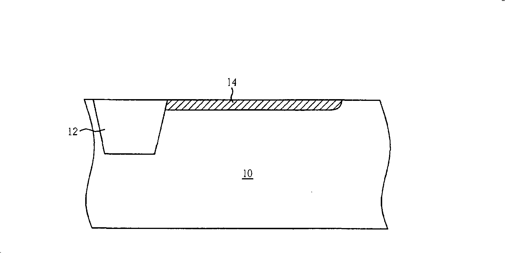
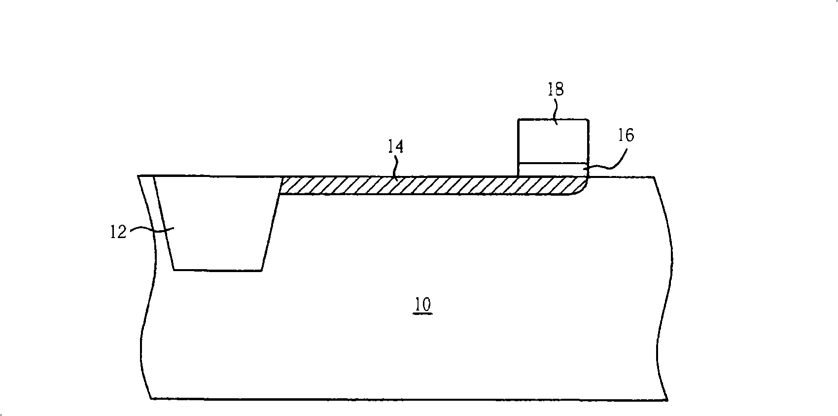
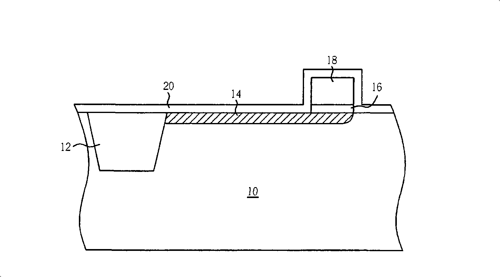
[0052] Please refer to Figure 15 to Figure 19 , Figure 15 to Figure 19 It is a schematic diagram of a method for fabricating a photosensitive diode according to a preferred embodiment of the present invention.

[0053] Such as Figure 15 As shown, firstly, a substrate 40 is provided, which at least includes a P-type doped well 41 and an STI structure 42 formed in the substrate 40 . As is well known to those skilled in the art, for example, the doping well process can be performed first, and then at least one trench (not shown) is formed in the substrate 40, and an insulating layer (not shown) is completely covered and filled on the surface of the substrate 40. trenches, and STI structures 42 are then formed in substrate 40 using chemical mechanical polishing. Wherein, the STI structure 42 is used to isolate each pixel unit of the active pixel sensor from each other, and it can also be replaced by other insulating structures such as a field oxide layer (FOX). Then P-type ...


PUM


Abstract

The invention discloses a manufacturing method of a photosensitive diode, comprising: firstly providing a substrate comprising a doping well; then forming a first doping region in the doping well; and then making use of an epitaxial process on the surface of the first doping region to form a conducting layer and meanwhile in-situ dopes the conducting layer to form a second doping region on the surface thereof. The manufacturing method of the photosensitive diode of the invention is mostly characterized in avoiding that the lattice structure of the surface is injected by high dose doping agent to be destroyed in the craftwork, thereby effectively reducing a dark current value generated in the non-light state and improving the sensitivity of the photosensitive diode.

Description

technical field [0001] The invention relates to a method for making a photosensitive diode, in particular to a method for making a photosensitive diode that can avoid damage to a crystal lattice in a photosensitive region during ion implantation. Background technique [0002] Complementary metal-oxide semiconductor (CMOS) image sensor (image sensor) is a common solid-state image sensing device nowadays, and CMOS image sensor has gradually replaced charge-coupled device (charge-coupled device) -coupled device (CCD) trend, because CCD has high power consumption, complicated process, and is not easy to integrate with control circuit or signal processing circuit, so it is difficult to reduce the size of CCD chip. The CMOS image sensor is manufactured by traditional semiconductor technology, so it has the advantages of lower manufacturing cost and smaller device size. In addition, the CMOS image sensor also has high quantum efficiency (quantum efficiency) and low readout noise. ...

Claims


Application Information

Patent Timeline
Patent Type & Authority Applications(China)
IPC IPC(8): H01L31/18
CPCY02P70/50
Inventor 蓝邦强苏宗一郭建男苏昭安林恒庆李世伟洪伟钦
Owner UNITED MICROELECTRONICS CORP
Learn More