Low-alloy high-strength steel laser composite weld hardness control method

A composite weld and hardness control technology, used in welding equipment, manufacturing tools, metal processing equipment, etc., can solve the problem of lack of improvement of weld formation, and achieve reduction of microhardness, reduction of martensitic structure ratio, and reduction of martensitic structure. The effect of the content of the tensite structure

Inactive Publication Date: 2010-06-09
SHANGHAI JIAOTONG UNIV +1
View PDF5 Cites 2 Cited by
  • Summary
  • Abstract
  • Description
  • Claims
  • Application Information

AI Technical Summary

Problems solved by technology

[0004] After searching, it was also found that in 2004, Ni Yu of Huazhong University of Science and Technology described a hybrid laser and non-melting electrode arc hybrid welding in his master's thesis "Laser Arc Hybrid Welding and Laser Welding Ultra-low Carbon Steel Weld Magnetic Properties Research". The non-melting electrode arc body is placed in front of the laser beam along the welding direction, the workpiece is preheated by the non-melting electrode arc, and the laser beam is then irradiated on the molten pool, which improves the energy transfer efficiency of the laser beam, because the non-melting electrode arc cannot provide additional When welding thicker metal materials, it is often difficult to avoid weld formation defects above the workpiece. It depends entirely on the welding process parameters of the laser beam. Its role is limited to improving the laser energy conversion efficiency and lacks the ability to improve the weld formation. ability

Method used


Image

  • Low-alloy high-strength steel laser composite weld hardness control method
  • Low-alloy high-strength steel laser composite weld hardness control method

Examples


Embodiment 1

[0029] This embodiment is used for welding low-alloy high-strength steel with dimensions of 250mm×100mm×10mm (length×width×thickness).

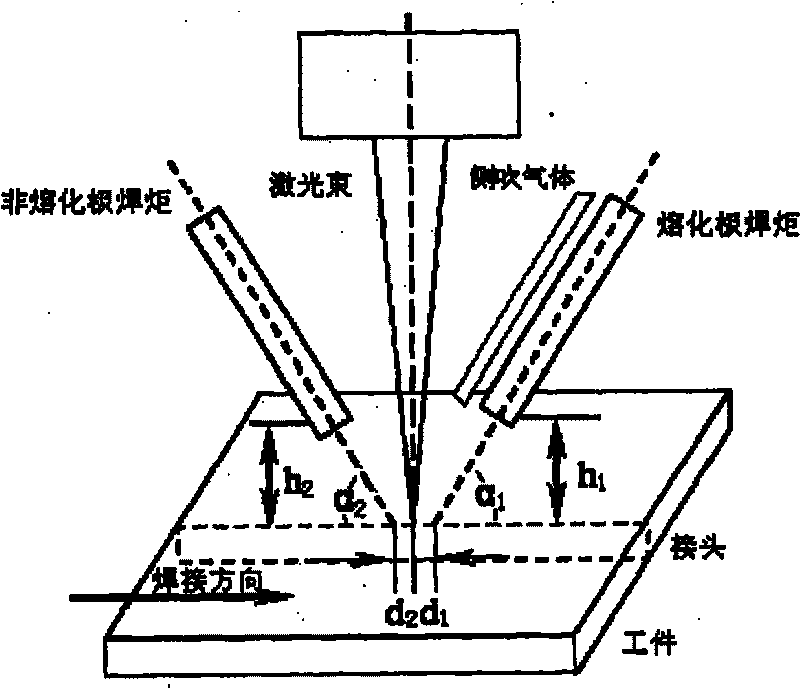
[0030] Such as figure 1 As shown, in this embodiment, the melting electrode arc heat source, laser heat source, and non-melting electrode arc heat source are arranged on a straight line along the welding direction in the order of acting on the workpiece, and the melting electrode arc is placed in front of the laser focus along the welding direction. By controlling the distance between the melting electrode arc and the laser focal point, the photoinduced plasma of the laser and the melting electrode arc plasma maintain interaction to form a molten pool together. The molten pool is shallow in the area covered by the melting electrode arc, while in the photoplasm The area is deep; the non-melting electrode arc is placed behind the laser focus along the welding direction, and the distance between the non-melting electrode arc and the laser focus ...

Embodiment 2

[0035] This embodiment is used for welding low-alloy high-strength steel with dimensions of 250mm×100mm×4mm (length×width×thickness).

[0036] The steps of this embodiment are the same as those of Embodiment 1, except that the welding parameters are adjusted, as follows:

[0037] Laser power:

8KW (laser output power)

Defocus amount:

-1mm (the laser focus is located 4mm below the upper surface of the sample)

Arc parameters:

280A, 21V (melting electrode arc)

[0038] Laser power:

8KW (laser output power)

150A, 17V (non-melting electrode arc)

Welding speed:

2.2m / min

Laser side blowing gas:

Pure helium, 20L / min

Arc shielding gas for melting electrode:

80% argon + 20% carbon dioxide, 15L / min

Non-melting electrode arc shielding gas:

Pure argon, 10L / min

Heat source spacing:

3mm (distance between melting electrode arc and laser)

5mm (distance between non-m...


PUM

PropertyMeasurementUnit
thicknessaaaaaaaaaa
heightaaaaaaaaaa
heightaaaaaaaaaa

Abstract

The invention relates to a method for controlling the hardness of low-alloy high-strength steel laser composite welds, which belongs to the technical field of welding engineering. In the invention, consumable electrode arc is positioned before the laser focus along the welding direction, the distance between the consumable electrode arc and the laser focus is controlled, so as to lead interactionto be maintained between the laser induced plasma of the laser and the plasma of the consumable electrode arc and to form a molten pool; the molten pool is shallow in the covering area of the consumable electrode arc, and deep in the laser induced plasma area; non-consumable electrode arc is positioned behind the laser focus along the welding direction, the distance between the non-consumable electrode arc and the laser focus is controlled, so that no marked interaction can appear between the laser induced plasma and the plasma of the non-consumable electrode arc, and simultaneously the non-consumable electrode arc is stably burnt with the assistance of the laser induced plasma. The method enhances the absorbing capacity of a work piece to the laser power, improves the bridging capabilityof laser welding, reduces the cooling rate of the welding seam and the microhardness of the connector, and improves the mechanical properties of the welding seam.

Description

technical field [0001] The invention relates to a method in the technical field of welding engineering, in particular to a method for controlling the hardness of a laser composite weld of low-alloy high-strength steel. Background technique [0002] Laser welding is a welding method characterized by high energy density, strong penetrating ability, and small heat input. It has been widely used in the connection of metal materials and non-metal materials. However, due to the difference in the laser absorption ability of the material itself and its surface state, the energy conversion efficiency of the laser to the welding workpiece is low, especially for CO 2 Gas laser, with a wavelength of 10.6 microns, has a high reflection coefficient when irradiating metal materials, and usually only a small part of the output laser power can be absorbed by the material as energy to melt the metal. On the other hand, the diameter of the laser beam spot is small, and it is highly sensitive ...

Claims


Application Information

Patent Timeline
Patent Type & Authority Patents(China)
IPC IPC(8): B23K28/02
Inventor 蔡艳倪加明倪慧峰俞海良张悦黄海谷
Owner SHANGHAI JIAOTONG UNIV
Why Eureka
Try Eureka