Ceramic composite pipe for conveying flue gas desulfurization glue size in electric power plant and method for manufacturing same

A ceramic composite, desulfurization slurry technology, applied in separation methods, chemical instruments and methods, pipes, etc., can solve the problems of increasing enterprise costs, poor erosion resistance, affecting the safe operation of power plant flue gas desulfurization devices, etc. Long service life effect

Inactive Publication Date: 2009-02-11
JINGANG NEW MATERIALS
View PDF0 Cites 13 Cited by
  • Summary
  • Abstract
  • Description
  • Claims
  • Application Information

AI Technical Summary

Problems solved by technology

At present, the flue gas desulfurization devices in power plants mainly use glass fiber reinforced plastic or plastic lined steel pipes. These materials have poor erosion resistance, especially in the bending part of the pipeline, the glass fiber reinforced plastic or plastic liners are easy to be worn out. Frequent replacement of pipelines not only increases the cost of enterprises, Moreover, it affects the normal operation of the desulfurization device, and even affects the production of the power plant.
Therefore, the slurry transportation pipeline has become an important issue affecting the safe operation of the flue gas desulfurization device in the power plant

Method used


Image

  • Ceramic composite pipe for conveying flue gas desulfurization glue size in electric power plant and method for manufacturing same

Examples


Embodiment 1

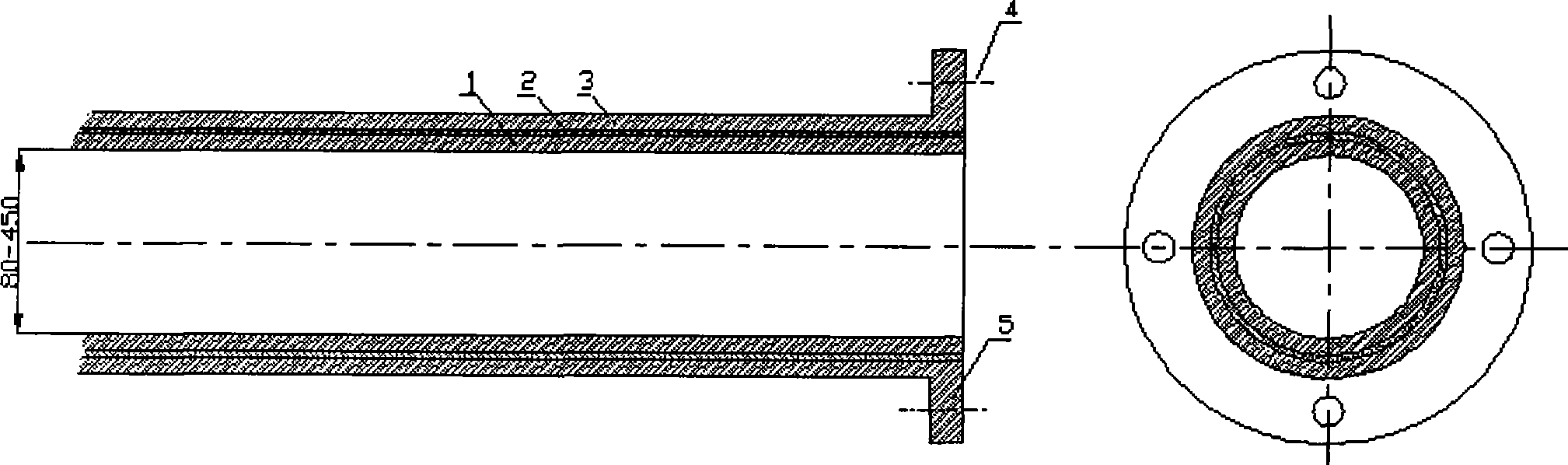
[0023] A ceramic composite pipe for flue gas desulfurization slurry transportation in a coal-fired power plant, characterized in that the inner pipe of the composite pipe is a ceramic pipe 1, the outer pipe is a metal pipe 3, and the middle layer between the inner and outer layers is a plastic pipe 2 . Described ceramic pipe 1 thickness is 5mm, and internal diameter is 180mm; Plastic pipe material is polyethylene (PE) plastics, and plastic pipe thickness is 2mm; Metal pipe selects common metal steel pipe, and the thickness of metal pipe is 4mm. It mainly plays the role of connecting and fixing the pipeline and protecting the inner layer from damage.

Embodiment 2

[0025] A ceramic composite pipe for conveying flue gas desulfurization slurry in a coal-fired power plant is characterized in that the inner layer pipe of the composite pipe is a ceramic pipe, the outer layer pipe is a metal pipe, and the middle layer between the inner layer and the outer layer is a plastic pipe. The ceramic tube has a thickness of 8 mm and an inner diameter of 300 mm. The material of the plastic tube is polyvinyl chloride (PVC) plastic tube, and the thickness of the plastic tube is 1 mm. The metal pipe is made of ordinary metal steel pipe, and the thickness of the metal pipe is 5mm.

Embodiment 3

[0027] (1) Forming of ceramic tube body:

[0028] 60 parts by weight of alumina powder, 6 parts by weight of calcium carbonate, 8 parts by weight of talc powder, 12 parts by weight of spodumene and 3 parts by weight of titanium oxide powder, and 20 parts by weight of kaolin are mixed according to a conventional amount of water and ball milled to prepare The slurry is spray-dried to obtain a mixed powder, and isostatically pressed to form a green body under a pressure of 80 MPa with an isostatic press;

[0029] (2) Place the dried green body at a temperature of 1460°C and fire it for 8 hours to obtain a ceramic tube;

[0030] (3) Select the plastic tube that fits the ceramic tube, put the ceramic tube in the plastic tube, and then put the ceramic tube and the plastic tube in the metal tube, and the metal tube and the plastic tube fit together, layer by layer The layers are glued and connected to form a ceramic composite pipe.


PUM

PropertyMeasurementUnit
thicknessaaaaaaaaaa
thicknessaaaaaaaaaa
thicknessaaaaaaaaaa

Abstract

The invention relates to a ceramic composite pipe used for conveying stack gas desulphurization slurry from electric power plants. An inner layer of the composite pipe is a ceramic pipe and an outer layer is a metal pipe; the interface layer between the inner layer and the outer layer is a plastic pipe; the inner diameter of the composite pipe ranges from 80mm to 450mm. The ceramic composite pipe is characterized by having anti-corrosion and anti-wearing property and long service life.

Description

technical field [0001] The invention relates to a corrosion-resistant and wear-resistant ceramic pipe for transporting flue gas desulfurization slurry in a coal-fired power plant and a manufacturing method thereof, belonging to the technical field of coal-fired power flue gas desulfurization. Background technique [0002] In the flue gas limestone-gypsum wet desulfurization process of coal-fired power plants, the limestone used as a desulfurization absorbent is ground into a slurry by crushing balls, which is transported to the spray absorption tower through a pipeline, and reacts with sulfur dioxide in the flue gas to form gypsum. So as to achieve the purpose of removing sulfur dioxide. Because the limestone slurry is highly corrosive and contains particles, the slurry will have a strong erosion and corrosion effect on the pipeline during the transportation process. At present, the flue gas desulfurization devices of power plants mainly use glass fiber reinforced plastics ...

Claims


Application Information

Patent Timeline
Patent Type & Authority Applications(China)
IPC IPC(8): F16L9/14B01D53/80B28B21/72C04B35/10
Inventor 赵友谊崔洪王晋槐张玉军
Owner JINGANG NEW MATERIALS
Why Eureka
Try Eureka