Ignition control carburetor of internal combustion engine

An ignition control and carburetor technology, which is applied in spark ignition controllers, carburetors, engine ignition, etc., can solve the problems of complex structure, mutual interference of magnetic sensors, high manufacturing cost, etc., achieve simple and compact structure, improve the overall The effect of low performance and manufacturing cost

Inactive Publication Date: 2011-02-09
LONCIN MOTOR
View PDF0 Cites 0 Cited by
  • Summary
  • Abstract
  • Description
  • Claims
  • Application Information

AI Technical Summary

Problems solved by technology

[0002] The ignition advance angle of the internal combustion engine is generally determined by the igniter according to the speed of the internal combustion engine, but the requirements for the ignition advance angle of the internal combustion engine are more complicated. There is a time difference from when the driving force is applied to the accelerator (carburetor plunger) to when the engine speed starts to increase. In fact, it is not very ideal to determine the advance angle solely by the rotational speed. For example, the ideal advance angle is different under the conditions of constant speed, slow acceleration, and rapid acceleration, so it is impossible to obtain an accurate ignition advance angle.
In order to solve the above problems, a throttle position sensor structure appears, and the position sensor is set correspondingly to the throttle driving lever or the driving handle. More accurate ignition advance angle; however, because the sensor indirectly measures the throttle opening, the transmission error will cause data acquisition errors in the position sensor, which will cause the electronic control unit to send an error control signal to the igniter. Feedback to the throttle can cause throttle control issues
At the same time, the installation of this structural sensor makes the overall structure of the vehicle uncoordinated, and the sensor is easily damaged by external force
In addition, four magnetic sensors are installed axially on the wall of the carburetor plunger cavity to directly detect the axial movement position of the plunger, thereby obtaining a more accurate ignition advance angle; although this structure eliminates the influence of transmission errors, but Since the plunger stroke is relatively short and the distance between the magnetic sensors is short, it will cause mutual interference between the magnetic sensors. Therefore, effective shielding measures are required, and the manufacturing cost is relatively high, and the structure is relatively complicated.

Method used


Image

  • Ignition control carburetor of internal combustion engine
  • Ignition control carburetor of internal combustion engine
  • Ignition control carburetor of internal combustion engine

Examples


Embodiment Construction

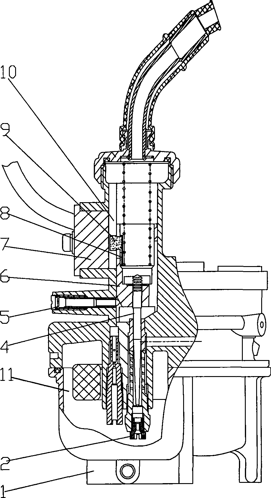
[0013] figure 1 It is a structural schematic diagram of the present invention, as shown in the figure: the internal combustion engine ignition control carburetor of this embodiment is an internal combustion engine carburetor for motorcycles, including a carburetor body 1, an air intake system, an oil intake system and an idle speed adjustment system 5 , the oil inlet system includes a float chamber 11, a main nozzle 2, an oil needle 4 and a plunger 6 axially fixedly connected to the oil needle 4, and the plunger 6 is arranged in the plunger chamber 10 in an axially movable manner, It also includes a Hall position sensor 7 and a permanent magnet 9, the Hall position sensor 7 is arranged on the wall of the plunger cavity 10, the permanent magnet 9 is arranged on the plunger 6 opposite to the Hall position sensor 7 in radial position, the permanent magnet 9 and the The radial gap between the Hall position sensors 7 is 2-3mm. If the gap is too small, the signal acquisition accurac...


PUM


Abstract

The invention discloses an internal-combustion engine ignition control carburetor which comprises a carburetor body, an air intake system, an oil inlet system and an idle speed regulation system; the oil inlet system comprises a floater chamber, a main nozzle, an oil needle and a plunger fixedly and coaxially connected with the oil needle; the plunger is arranged in the plunger cavity and able tomove axially in the plunger cavity; the oil inlet system also comprises a hall position sensor and a permanent magnet; the hall position sensor is arranged on the cavity wall of the plunger; the permanent and the hall position sensor are arranged on the plunger with the opposite radial positions; the internal-combustion engine ignition control carburetor adopts the hall position sensor to generate the square wave signal under the effect of the permanent magnet to directly detect the axial movement position of the plunger and eliminate the influence on the signal acquisition caused by the transmission error; more accurate ignition advance angle is obtained according to the position signal; the disturbance problem from the advance angle is avoided; because the position signal of the plungeris acquired directly, the distribution of a plurality of sensors are avoided so that the structure is simple and compact; the manufacturing cost is low, the whole performance of the internal-combustion engine is improved.

Description

technical field [0001] The invention relates to a carburetor for an internal combustion engine, in particular to an ignition control carburetor for an internal combustion engine. Background technique [0002] The ignition advance angle of the internal combustion engine is generally determined by the igniter according to the speed of the internal combustion engine, but the requirements for the ignition advance angle of the internal combustion engine are more complicated. There is a time difference from when the driving force is applied to the accelerator (carburetor plunger) to when the engine speed starts to increase. In fact, it is not very ideal to determine the advance angle solely by the rotational speed. For example, the ideal advance angles are different under the conditions of constant speed, slow acceleration, and rapid acceleration, so it is impossible to obtain an accurate ignition advance angle. In order to solve the above problems, a throttle position sensor stru...

Claims


Application Information

Patent Timeline
Patent Type & Authority Patents(China)
IPC IPC(8): F02M7/14F02M19/00F02P7/07
Inventor 石晓东邓志勇徐斌彭发碧
Owner LONCIN MOTOR
Why Eureka
Try Eureka