Method for producing friction material with ceramic fibre
A ceramic fiber and friction material technology, applied in the field of friction materials
Inactive Publication Date: 2009-04-08
信义集团公司
View PDF0 Cites 8 Cited by
- Summary
- Abstract
- Description
- Claims
- Application Information
AI Technical Summary
Problems solved by technology
[0003] The purpose of this invention is to solve the problems existing in the batching process of the existing friction materials, and propose a method of using ceramic fiber friction material reinforcement and friction performance regulator to improve the heat resistance, decay resistance and impact resistance of friction materials Method for preparing friction material by using ceramic fiber which prolongs service life and improves corresponding comprehensive performance of friction material
Method used
View moreImage
Smart ImageViewing Examples
Examples
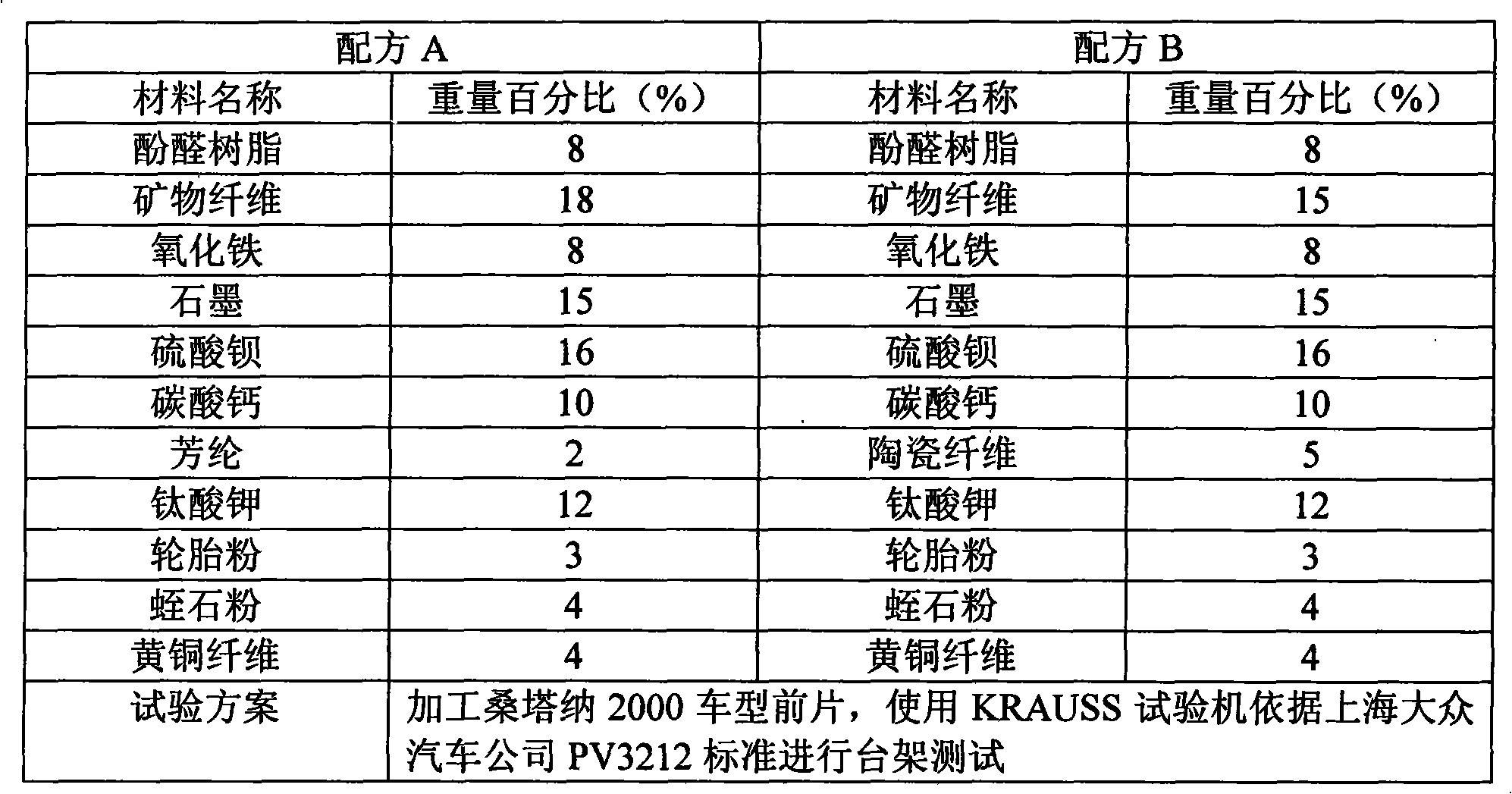
Embodiment Construction
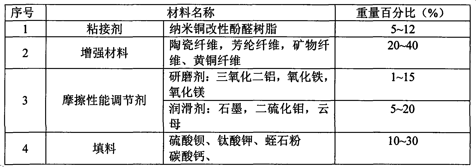
[0007] The formula used in the present invention is as follows:
[0008]
Login to View More PUM
 Abstract
The invention relates to a method for preparing a friction material by using ceramic fiber in the friction material field. The technical proposal is characterized in that resin, fiber, an abrasive, a lubricant and filler are provided with such processing steps as batch mixing, molding and hot briquetting, heat treatment, grinding and inspection to obtain the friction material. The resin used is nano-copper modified phenolic resin; the fiber is a combination of ceramic fiber and aramid fiber or mineral fiber, wherein, the dosage of the ceramic fiber is 2 portions to 5 portions by weight; the abrasive comprises aluminum oxide, iron oxide or magnesium oxide; and the lubricant comprises graphite, molybdenum disulfide or mica, the filler comprises barium sulfate, calcium carbonate, potassium titanate or vermiculite powder. The method aims at utilizing the advantages of ceramic fiber, such as high melting point, high molar quantity, stable compression property and excellent chemical resistance stability and good flexibility in the design of friction material formula. The friction material does not incur heat fading at high temperature and has stable friction factor, little abrasion and impact strength improved by approximately 30 percent. The friction material leads to a comfortable braking when being used without producing noises and the service life is more than 70 thousand kilometers.
Description
technical field [0001] The present invention relates to a method for preparing friction materials using ceramic fibers in the field of friction materials. Background technique [0002] The friction material preparation process for brake pads usually includes the following components: resins, fibers, abrasives, lubricants and fillers. Its processing technology mainly includes batching-mixing-molding-grinding-inspection-packaging and other processes. Brake pads, which are key parts of automobiles, are currently being developed from single materials to composite materials, and their quality directly affects the reliability of machines and the safety of operators. The speed, load and safety requirements of machinery are getting higher and higher, high-speed trains, heavy-duty trucks, cars, racing cars, motorcycles and other heavy-duty, high-speed driving, and frequent braking civilian vehicles, as well as armored vehicles and tanks that use harsh environments , helicopters, et...
Claims
Login to View More Application Information
Patent Timeline
 IPC IPC(8): C08L61/14C08K13/04C08K7/04C08J5/14C08K3/22C08K3/04C08K3/30C08K3/34
Inventor 延军
Owner 信义集团公司
Features
- R&D
- Intellectual Property
- Life Sciences
- Materials
- Tech Scout
- Unparalleled Data Quality
- Higher Quality Content
- 60% Fewer Hallucinations
Learn More Browse by: Latest US Patents, China's latest patents, Technical Efficacy Thesaurus, Application Domain, Technology Topic, Popular Technical Reports.
© 2025 PatSnap. All rights reserved.Legal|Privacy policy|Modern Slavery Act Transparency Statement|Sitemap|About US| Contact US: help@patsnap.com


