Method for prolonging the life of liquid-phase fluorination catalyst

A fluorination catalyst and life-span technology, applied in physical/chemical process catalysts, chemical instruments and methods, chemical recovery, etc., can solve problems such as impurities or corrosion, easy deposition, and low effect, and achieve high reaction selectivity and yield , improve the mass transfer condition, and use for a long time

Inactive Publication Date: 2009-05-06
JUHUA GRP
View PDF2 Cites 1 Cited by
  • Summary
  • Abstract
  • Description
  • Claims
  • Application Information

AI Technical Summary

Problems solved by technology

[0004] However, the biggest problem in the application of the previous technology in industrial devices is that due to factors such as material corrosion and pressure, it is difficult to install a stirrer in the reactor, so the mass transfer effect in the reactor is poor, the surface of the catalyst is less renewed, and it is easy to deposition
For example, the activation method of introducing a small amount of chlorine gas can play a certain role, but because the amount of chlorine passing is strictly limited, impurities or corrosion problems will occur if the amount of chlorine passing is slightly larger, which will increase the burden of follow-up treatment, and the mass transfer in the reactor still remains Very poor, the catalyst has less contact opportunities with the activator chlorine, and the activation effect is limited, especially in the later stage of the reaction, it is more obvious
Another example is the hydrofluoric acid insertion tube method. Although the hydrofluoric acid is vaporized and fed through the insertion tube, there is a certain bubbling effect, but because the flow rate is too small, the actual effect is very small.
However, the method of taking out the catalyst in the reactor and adding it back after fluorination is difficult to implement industrially.

Method used


Image

  • Method for prolonging the life of liquid-phase fluorination catalyst
  • Method for prolonging the life of liquid-phase fluorination catalyst
  • Method for prolonging the life of liquid-phase fluorination catalyst

Examples


Embodiment 1

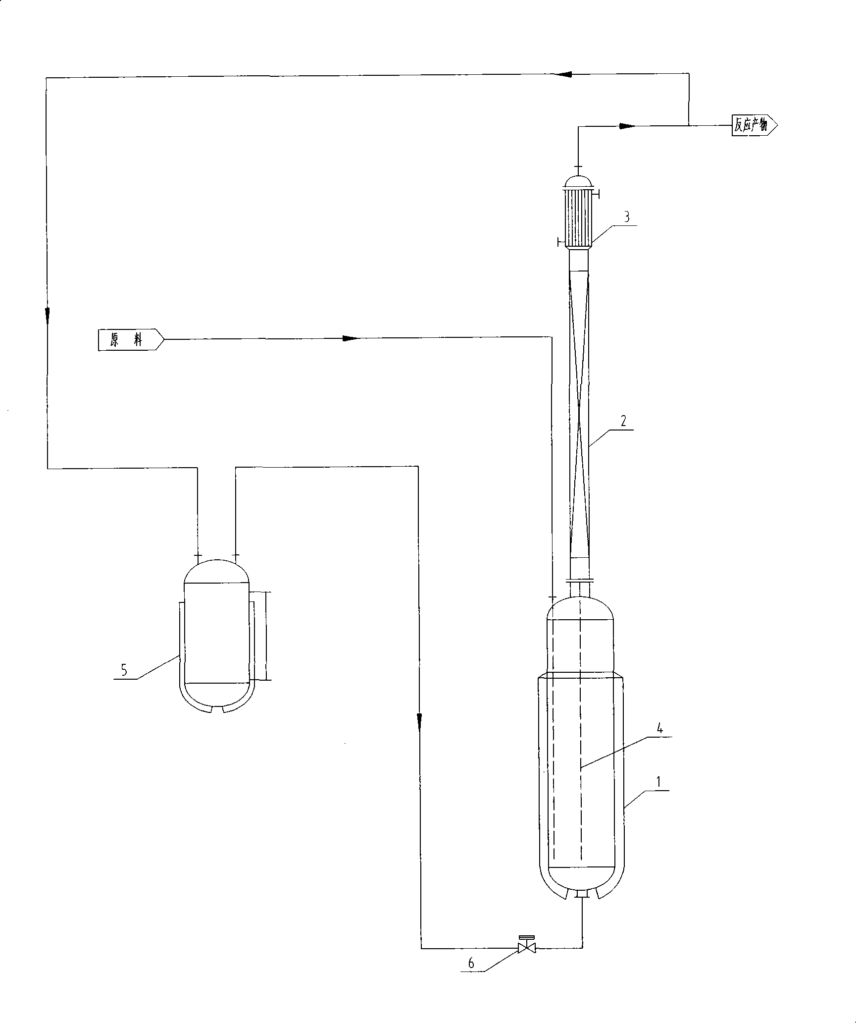
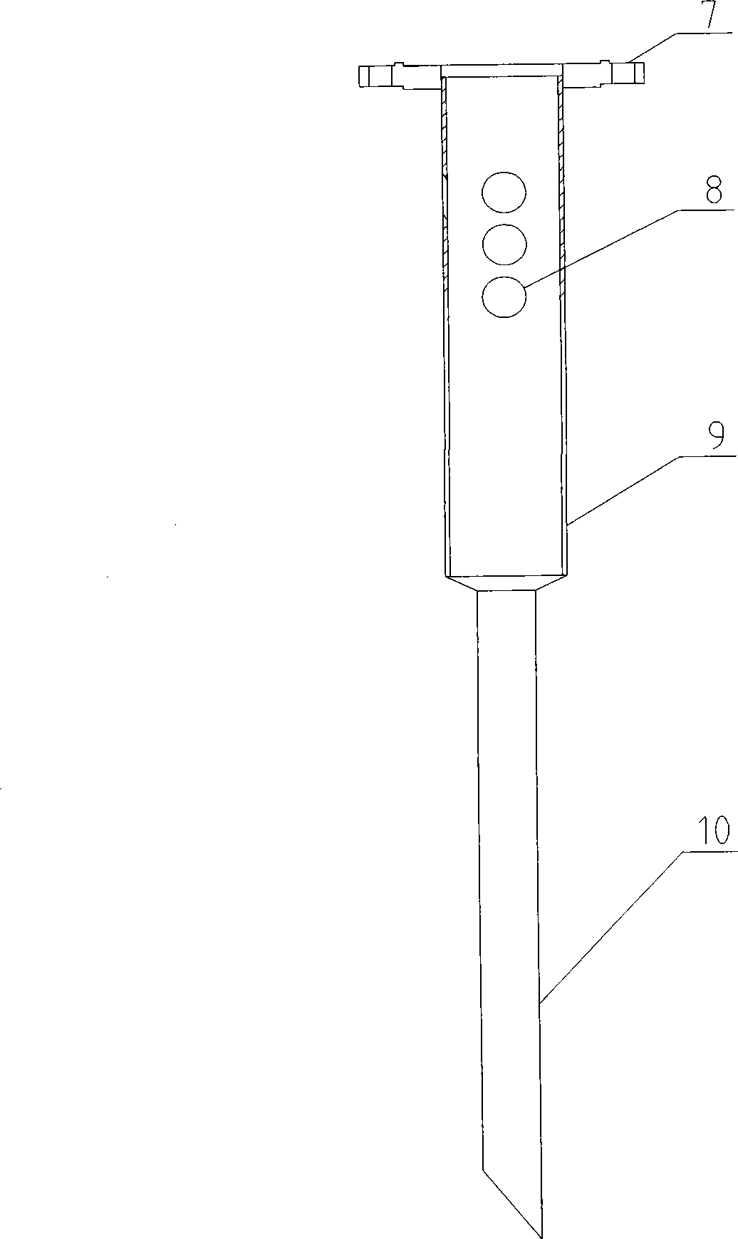
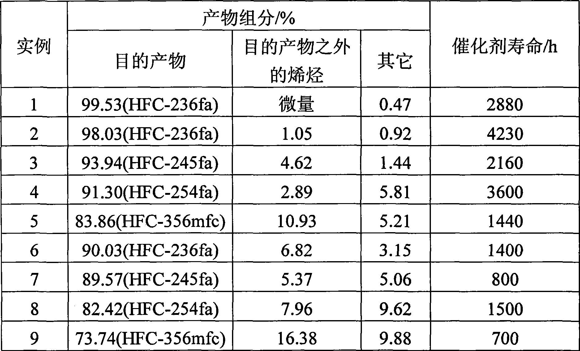
[0021] In a 50L fluorination reactor, add 25kg of antimony pentachloride. HCC-230 and AHF are continuously fed into the reactor in a ratio of 1:5~6mol / mol. During the reaction process, chlorine gas was continuously introduced, and the total amount was 0.001 of the moles of HCC-230. The fluorination reactor controls the kettle temperature to 70-90°C, the top temperature to 15-35°C, and the reactor pressure to 1000-1300kPa. The HFC-236fa (content 99%) returned to the fluorination reactor is heated, vaporized and pressurized to 1100-1400kPa by a pulsation device, and then introduced into the fluorination reactor at a rate of 1 time / h and 3 min / time. The reaction product is washed to remove inorganic acid, collected after condensation and liquefaction, and analyzed for component content. Catalyst life and product component content are shown in Table 1.

Embodiment 2

[0023] In a 1000L fluorination reactor, add 500kg of antimony pentachloride. HCC-230 and AHF are continuously fed into the reactor in a ratio of 1:5~6mol / mol. During the reaction process, chlorine gas was continuously introduced, and the total amount was 0.001 of the moles of HCC-230. The fluorination reactor controls the kettle temperature to 70-90°C, the top temperature to 15-35°C, and the reactor pressure to 1000-1300kPa. The HFC-236fa (content 95%) returned to the fluorination reactor is heated, vaporized and pressurized to 1100-1400kPa by a pulsation device, and then introduced into the fluorination reactor at 2 times / h and 3min / time. The reaction product is washed to remove inorganic acid, collected after condensation and liquefaction, and analyzed for component content. Catalyst life and product component content are shown in Table 1.

Embodiment 3

[0025] In a 50L fluorination reactor, add 25kg of antimony pentachloride. HCC-240 and AHF are continuously fed into the reactor in a ratio of 1:5~6mol / mol. During the reaction process, chlorine gas was continuously introduced, and the total amount was 0.001 of the moles of HCC-240. The fluorination reactor controls the kettle temperature to 70-90°C, the top temperature to 15-35°C, and the reactor pressure to 1000-1300kPa. The HFC-245fa (with a content of 90%) returned to the fluorination reactor is heated and vaporized by a pulsation device to increase the pressure to 1100-1400kPa, and then introduced into the fluorination reactor at 2 times / h and 3min / time. The reaction product is washed to remove inorganic acid, collected after condensation and liquefaction, and analyzed for component content. Catalyst life and product component content are shown in Table 1.


PUM


Abstract

The invention discloses a method for prolonging the service life of a liquid fluorination catalyst, which comprises following steps: (1) an antimony halide catalyst is firstly added into a reactor, raw materials of AHF and hydrochloric ether are continuously added, and chlorine gas is introduced, thus obtaining a rough hydrofluoric ether product after reaction; (2) the rough hydrofluoric ether product is rinsed for removing an inorganic acid, the rough hydrofluoric ether product is collected after condensed liquefaction, and the total 97 to 99 percent of rough product is distilled, thus obtaining a hydrofluoric ether product; and (3) the total 1 to 3 percent of rough hydrofluoric ether product is heated, vaporized and pressure increased by an impulsive device, and then returned to the reactor for being recycled. By arranging a guide tube inside the reactor, the method leads the top condensed materials to return to the liquid phase of the reactor, and simultaneously adds the gas impulsive device for introducing gas medium is into the reactor, improving mass transferring state inside the reactor, and increasing contact probability of alkyl halide, an activating agent and the catalyst, thus effectively prolonging the service life of the liquid fluorination catalyst. The method has the advantages of high reaction selectivity and yield, long catalyst use time and less device investment, etc.

Description

technical field [0001] The present invention relates to catalysts, in particular to a method for prolonging the service life of liquid-phase fluorination catalysts. Background technique [0002] When using antimony halide, tin halide, titanium halide and other catalysts, especially antimony halide, to carry out liquid-phase fluorination of hydrogen fluoride and halogenated hydrocarbons, due to the corrosiveness of the reaction materials and system pressure, etc., the dynamic sealing requirements are strict, and it is difficult to install on the reactor. Stirring device, plus the organic high boiling colloid (mainly C 2 ~C 4 Olefin adducts) on the surface of the catalyst, and the catalytic conversion of pentavalent antimony to trivalent antimony leads to partial solidification and deposition of the catalyst, which shortens the life of the fluorination catalyst and cannot fully meet the needs of industrial production. [0003] Known methods, such as feeding a small amount of...

Claims


Application Information

Patent Timeline
Patent Type & Authority Applications(China)
IPC IPC(8): B01J27/32C07C17/20
CPCY02P20/584
Inventor 王树华吴国颖张文革
Owner JUHUA GRP
Why Eureka
Try Eureka