
Controller and controlling method for non-bearing permanent magnet synchronous electric motor

A technology of permanent magnet synchronous motor and control method, which is applied in the direction of motor generator control, AC motor control, electronic commutation motor control, etc., and can solve the problem of limiting suspension force control accuracy and dynamic response performance, and inverter capacity utilization. High, difficult to achieve the control effect and other problems, to achieve the effect of excellent dynamic and static performance, excellent motor performance, fast speed response

Inactive Publication Date: 2010-08-25
JIANGSU UNIV
View PDF0 Cites 0 Cited by
  • Summary
  • Abstract
  • Description
  • Claims
  • Application Information

AI Technical Summary

Problems solved by technology

In the traditional levitation force vector control, the system relies too much on the motor parameters and the complexity of vector coordinate transformation, making it difficult for the actual control effect to achieve the results of theoretical analysis; the levitation force is in an open-loop state, which limits the accuracy and dynamics of levitation force control Response performance; adopt current tracking inverter, the switching frequency of the inverter is high, and the utilization rate of the inverter capacity is not high

Method used


Image

  • Controller and controlling method for non-bearing permanent magnet synchronous electric motor
  • Controller and controlling method for non-bearing permanent magnet synchronous electric motor
  • Controller and controlling method for non-bearing permanent magnet synchronous electric motor

Examples


Embodiment Construction

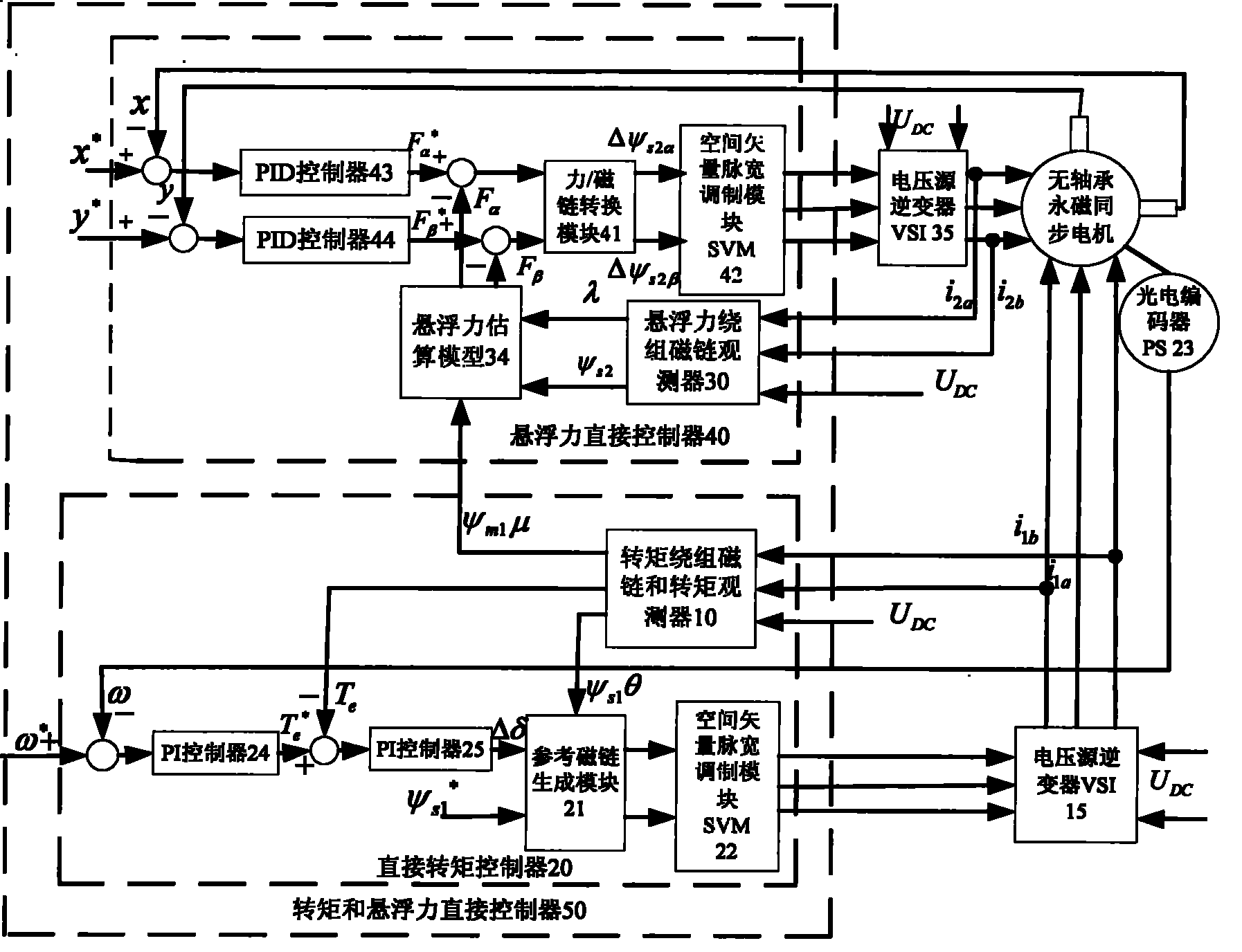
[0034] The embodiment of the present invention is: based on the prototype body of the bearingless permanent magnet synchronous motor, the direct control system of torque and levitation force is equivalent to two subsystems of direct control of torque and direct control of levitation force. For the torque direct control subsystem, construct a double closed loop with speed and torque consisting of two PI controllers, torque winding flux linkage and torque observer, reference flux linkage generation module and space vector pulse width modulation module SVM The direct torque control system, first use the torque winding flux and torque observer to obtain the torque winding flux and torque information required by the direct torque control; then the observed torque winding real-time flux and torque The torque information is applied to the direct torque controller to generate the switching signal of the torque winding control voltage source inverter, and drive the inverter to directly ...


PUM


Abstract

The invention relates to a controller and a controlling method of a no-bearing permanent-magnetic synchronous motor. The controlling method comprises the following steps: a direct torque controller calculates magnetic linkage and a torque by torque winding magnetic linkage, a double-closing loop of a rotating speed and the torque is constructed, the increment of the phase angle of the magnetic linkage is generated by the comparing difference value of the instruction value and the real-time value of the rotating speed and the torque through double-P1 modulation, and a switch signal of an inverter of a power supply source is obtained by the modulation of SVM and a reference magnetic linkage generating module; a suspending power direct controller calculates the magnetic linkage by a winding magnetic linkage observer of the suspending power, the double-closing ring of rotor shift and the suspending power is constructed, the comparing difference value of the rotor shift generates a suspending power instruction value by PID modulation, and the switch signal of an inverter of a power supply is obtained by the rotor shift comparing difference value and the comparing difference value of the real-time value thereof after the modulation of SVM and a power / magnetic linkage converting module. The direct torque controller and the suspending power direct controller are used for forming the torque and suspending power direct controller to control the no-bearing permanent magnetic synchronous motor, and the controlling method has the advantages of simplicity and good effect.

Description

technical field [0001] The invention relates to the technical field of electric drive control equipment, in particular to a controller and a control method of a bearingless permanent magnet synchronous motor. Background technique [0002] Bearingless permanent magnet synchronous motor inherits the characteristics of non-lubrication, no wear and no mechanical noise of the magnetic bearing motor, and is used in special electrical transmissions such as machine tool spindles, turbomolecular pumps, centrifuges, compressors, electromechanical energy storage, and aerospace. The field has broad application prospects. Bearingless permanent magnet synchronous motor is a kind of multivariable, nonlinear and strongly coupled controlled object, and its radial position and speed are difficult to be accurately controlled by external signals. To achieve stable suspension and operation of the motor rotor, decoupling control of the motor torque and suspension force must be performed. [000...

Claims


Application Information

Patent Timeline
Patent Type & Authority Patents(China)
IPC IPC(8): H02P21/00H02P27/04H02N15/00H02P21/20H02P21/30
Inventor 谭耳朱熀秋
Owner JIANGSU UNIV
Learn More