Permanent magnet auto-conduction magnetic levitation magnetic force pressure generator

A technology of pressure generators and permanent magnets, applied to electrical components, electromechanical devices, etc., can solve the problems of irresistible water, gas, inevitable mechanical transmission friction, energy consumption, etc., to improve the cleanliness of the atmosphere and the quality of hygiene, reduce Effects of consumer spending and increased electricity supply

Inactive Publication Date: 2009-05-20
石才俊
View PDF0 Cites 8 Cited by
  • Summary
  • Abstract
  • Description
  • Claims
  • Application Information

AI Technical Summary

Problems solved by technology

[0002] At present, relevant reports: People want to use footsteps to generate electricity in the subway with a large flow of people, and have done a rubber pad device test, but the energy converted by the harvested energy is very small, and there are also pressure-generating shoes and ocean waves that are in the experimental stage or available for application. Most of the power generation technology and products rely on mechanical transmission to realize the conversion of force and electric energy, which inevitably leads to mechanical transmission friction, energy consumption, wear, noise and other problems
At the same time, due to the device composed of gears, connecting rods, shafts, bearings and other components necessary for mechanical transmission, it has great constraints on the space of the installation and use environment and it is difficult to meet some comfort requirements. In addition, it is difficult to seal. Can not resist the corrosion of water, air, especially sea water

Method used


Image

  • Permanent magnet auto-conduction magnetic levitation magnetic force pressure generator
  • Permanent magnet auto-conduction magnetic levitation magnetic force pressure generator
  • Permanent magnet auto-conduction magnetic levitation magnetic force pressure generator

Examples


Embodiment 1

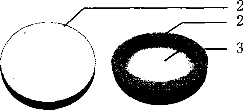
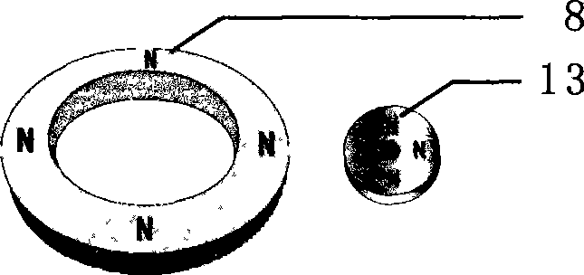
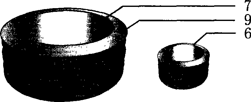
[0015] Choose a thin axially magnetized super permanent magnet ring and a permanent magnet with a central hole (see figure 2 -8, 13), and select moderate non-metallic materials to make an inverted basin-shaped pressure transmission element (2) (see Figure 1-2 ), the lining is lined with a cushioning anti-noise pad (3) (see Figure 1-3 ), firmly connect the permanent magnet ring (8) to the lower periphery of the pressure conductor (2), and install it in the outer conductive coil bobbin and the inner conductive coil bobbin that have been positioned and fixed concentrically on the assembly bottom plate (14), The permanent magnet with a central hole should be fitted on the guide rail (17) (see Figure 5). Before this, the guide rail (17), the reset elastic device (15), the lower buffer noise-proof elastic device (16), Permanent magnet (13) with a center hole (if the center hole is circular, the guide rail is a square cylinder; if the center hole is a square hole, the guide rail is a cyl...

Embodiment 2

[0017] The many permanent magnet self-induction magnetic levitation magnetic mortar-type pressure generators described in Example 1 are combined into various carpet mats of different sizes and placed on pedestrian passages (especially in places with a large flow of people, Such as subway station channels), harvest people’s walking pressure to generate electricity, and according to different power requirements, connect in series or parallel to power storage and energy storage devices to facilitate power supply.

Embodiment 3

[0019] The permanent magnet self-induction magnetic levitation mortar-type pressure generator described in Example 1 is made into a product of a certain specification, buried under the speed limit belt of the highway, and generated by the wheel rolling. Its installation can be a single parallel arrangement, or It can be superimposed and buried deeply, but the reset elastic device (15) should be opened, and the pressure transmission column should be installed one by one to firmly connect with the permanent magnet ring (8) above. When the external force (extrusion force) acts on the top pressure When the conducting piece (2), the external force (extruding force) is also transmitted to the conducting piece (2) below. In this installation method, no matter how many permanent magnets are superimposed, the self-induction magnetic levitation mortar pressure generator All of them need only one elastic corrugated sealing cover, which can reduce the cost and make it more convenient to use w...


PUM


Abstract

The invention provides a permanent-magnet self-inductance magnetic-suspension magnetic-mortar type pressure generator, which can be widely used in water, on land and in the air, fully utilizes and converts extruding force and reacting force to the ground in the production and living field of human beings, as well as wind power, flowing water power and wave force existing in the nature into electric energy, is superior to a single permanent-magnet reciprocating-motion pressure generator, and generates electricity with electricity magnetic energy. The generator can at least utilize one permanent magnetic ring, bears the action of external force to do reciprocating motion and cut a conductive coil through a magnetic force line so as to generate electric energy, and simultaneously shoots magnetic shots by using a magnetic cannon so as to mortar another permanent magnet to do reciprocating motion rapidly, thereby increasing the magnetic flux of a conductive coil winding in unit time and greatly improving power and stabilizing current and voltage. The force which is utilized to do work by the generator can be weak or quite strong. The generator consists of a pressure conducting piece sealed in an anticorrosion elastic corrugated seal cover, a buffer anti-noise pad, a positioning cover plate, the conductive coil winding and a framework thereof, the permanent magnetic ring, the permanent magnet with a central hole, a soft magnetic material hoop, a soft magnetic material, a reset elastic device, an upper buffer anti-noise elastic device, a lower buffer anti-noise elastic device, a guide rail and a final assembly bottom board. The generator is a generating device which has no gear, connecting rod or other mechanical transmission system, produces no noise, needs no lubrication, and can prevent water as well as gas corrosion.

Description

Technical field [0001] The present invention provides a device that can be widely used in water, land, and air, and fully utilizes the squeezing force and reaction force of human beings on the ground in the fields of production and life, as well as the wind, current, and wave forces existing in nature, so that The permanent magnet self-induction magnetic levitation magnetic mortar-type pressure generator that converts into electrical energy. It uses the power of work, which can be very weak or very powerful. Background technique [0002] Current reports: People want to use footsteps to generate electricity in a subway with a large flow of people, and have done a rubber pad device test, but the energy converted by the harvested energy is very small, and there are also pressure-generating shoes and waves that are in the experimental stage or are commercially available. Most of the power generation technologies and products rely on mechanical transmission to achieve the conversion o...

Claims


Application Information

Patent Timeline
Patent Type & Authority Applications(China)
IPC IPC(8): H02K35/02
Inventor 石才俊
Owner 石才俊
Why Eureka
Try Eureka