Method for improving ferro-nickel alloy plating weldability

A nickel-iron alloy, solderability technology, applied in the field of microelectronic materials, to achieve the effect of simple process, good solderability, and improved oxidation state

Inactive Publication Date: 2009-06-10
INST OF METAL RESEARCH - CHINESE ACAD OF SCI
View PDF0 Cites 3 Cited by
  • Summary
  • Abstract
  • Description
  • Claims
  • Application Information

AI Technical Summary

Problems solved by technology

[0007] The object of the present invention is to provide a kind of method for improving the weldability of nickel-iron alloy coating, solve the problems such as the weldability of nickel-iron alloy coating as UBM material, by protecting the surface of nickel-iron alloy coating, reduce its chance of contact with oxygen etc., To improve the oxidation state of the nickel-iron alloy coating and maintain good weldability of the alloy coating

Method used


Image

  • Method for improving ferro-nickel alloy plating weldability
  • Method for improving ferro-nickel alloy plating weldability
  • Method for improving ferro-nickel alloy plating weldability

Examples


Embodiment 1

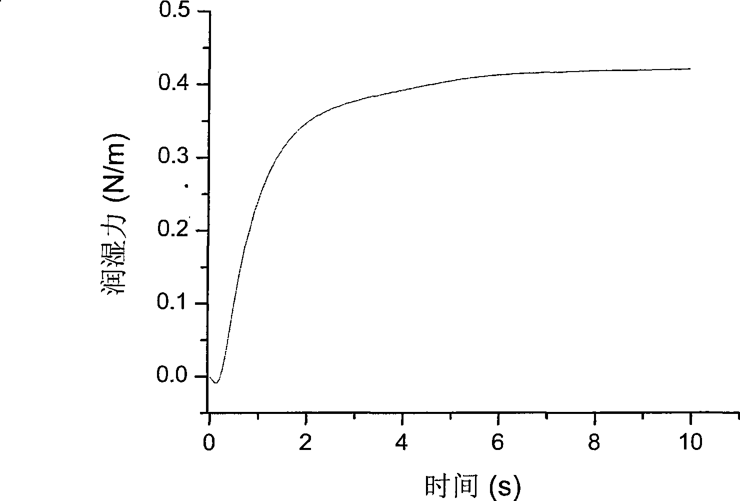
[0028] The electroplating method is used to electroplate a coating composed of Ni-47Fe on a rectangular copper sheet of 20×10 mm. The thickness of the nickel-iron alloy coating in this embodiment is 7 μm. After electroplating, the samples were washed with distilled water and dried. Put into the electroless gold-plating liquid and carry out gold-plating, the gold-plating liquid that chemical gold-plating uses is the cyanide-free gold-plating solution with gold chloride as gold salt. The gold plating temperature was controlled at 50° C. for 10 minutes, and the thickness of the gold protective film obtained in this embodiment was 0.6 um. Using SKC-8H solderability tester for solderability test, the results are as follows figure 1 As shown, from the test results, the sample has good solderability.

Embodiment 2

[0034] Using the same electroplating method and electroless plating method, by controlling the ratio of Ni and Fe ions in the electroplating solution, a Ni-71Fe coating with gold plating on the surface is prepared. In this embodiment, the thickness of the nickel-iron alloy coating is 7um, and the thickness of the obtained gold protective film is 0.6um. The solderability of the samples was tested using a solderability tester, and the results were as follows Figure 4 As shown, it can be seen that the solderability of the coating is good.

Embodiment 3

[0040] Use the same electroplating method to electroplate the nickel-iron alloy coating, and plate gold on the coating surface for 5 minutes. In this embodiment, the thickness of the nickel-iron alloy coating is 7um, and the thickness of the obtained gold protective film is 0.45um. The solderability was tested with a solderability tester. The data are shown in Table 3. It can be seen that the solderability of the coating is good, but the wetting time is slightly longer than that of the sample plated with gold for 10 minutes, and the maximum wetting force remains unchanged.

[0041] table 3

[0042] Ni-47Fe Gilded for 5 minutes Gilded for 10 minutes Gilded for 20 minutes Start wetting time (t b ) / s 0.13±0.03 0.11±0.03 0.14±0.03 Maximum wetting force (F max )N / m 0.41±0.01 0.41±0.01 0.41±0.01


PUM


Abstract

The invention belongs to the technical field of microelectronic material, in particular to a method for improving solderability of a copernik cladding, which improves the surface of the copernik cladding, reduces oxidation degree of the surface, and acquires the surface with excellent solderable performance, through plating gold on the surface of the copernik cladding. The method solves solderability and other problems of the copernik cladding as a UBM material, protects the surface of the copernik cladding, and reduces the opportunity for the cladding to contact with oxygen and the like, thereby improving the oxidation state of the copernik cladding, and maintaining the excellent solderability of the copernik cladding. The gold-plated coating on the surface of the copernik cladding can be used as a surface finishing cladding to directly carry out soldering on the cladding, and is applicable to various soldering technologies, in particular to the microelectronic encapsulation industry.

Description

technical field [0001] The invention belongs to the technical field of microelectronic materials, in particular to a method for improving the weldability of a nickel-iron alloy coating. Background technique [0002] Advanced interconnect technologies, such as flip-chip technology, have been widely used in the microelectronics industry today. In this technology, the electrode surface of the chip and the solder bump are connected through a metal transition layer (UBM). The main function of this metal transition layer is to conduct current and reduce the thermal stress between the chip and the solder due to the difference in thermal expansion coefficient. [0003] Therefore, UBM materials are required to have the characteristics of low thermal expansion coefficient, good weldability, and reliable interface connection. [0004] Due to the serious threat to the environment and human health due to the metal lead rich in traditional solder, the call for banning the use of lead in...

Claims


Application Information

Patent Timeline
Patent Type & Authority Applications(China)
IPC IPC(8): C23C30/00C25D3/48C23C18/31B23K35/22
Inventor 王慧生张磊尚建库
Owner INST OF METAL RESEARCH - CHINESE ACAD OF SCI
Why Eureka
Try Eureka