Production method for sensitivity enhanced extrinsic F-P optical fiber temperature sensor

An optical fiber temperature and manufacturing method technology, applied in the field of sensors, can solve the problems of difficult sensors, slow temperature response, slow temperature response, etc., and achieve the effects of high temperature sensitivity, good fiber end face, and fast temperature response

Inactive Publication Date: 2009-07-08
DALIAN UNIV OF TECH
View PDF0 Cites 17 Cited by
  • Summary
  • Abstract
  • Description
  • Claims
  • Application Information

AI Technical Summary

Problems solved by technology

[0005] At present, the extrinsic F-P fiber optic temperature sensor is basically made of glass fiber and capillary glass tube, and the temperature sensitization effect is limited; the temperature sensitivity can be improved by sticking the extrinsic F-P fiber optic temperature sensor on a metal sheet or other materials with a large thermal expansion coefficient , but has the disadvantages of slow temperature response and large volume, and the influence of thermal stress on the measurement results needs to be considered
Because the glass capillary is thin, the extrinsic F-P fiber optic temperature sensor without any protection is easily damaged by extrusion and shearing of external force. The size is large and the temperature response speed is slow, so that the advantages of the original sensor cannot be fully displayed
[0006] When making extrinsic FP optical fiber sensors by traditional methods, it is necessary to cut out the flat end face of the optical fiber first, or obtain a flat end face of the optical fiber by grinding and polishing methods, and then operate the complete flat end face of the optical fiber un

Method used


Image

  • Production method for sensitivity enhanced extrinsic F-P optical fiber temperature sensor

Examples


Embodiment Construction

[0012] The best embodiment of the present invention will be described in detail below in conjunction with the accompanying drawings.

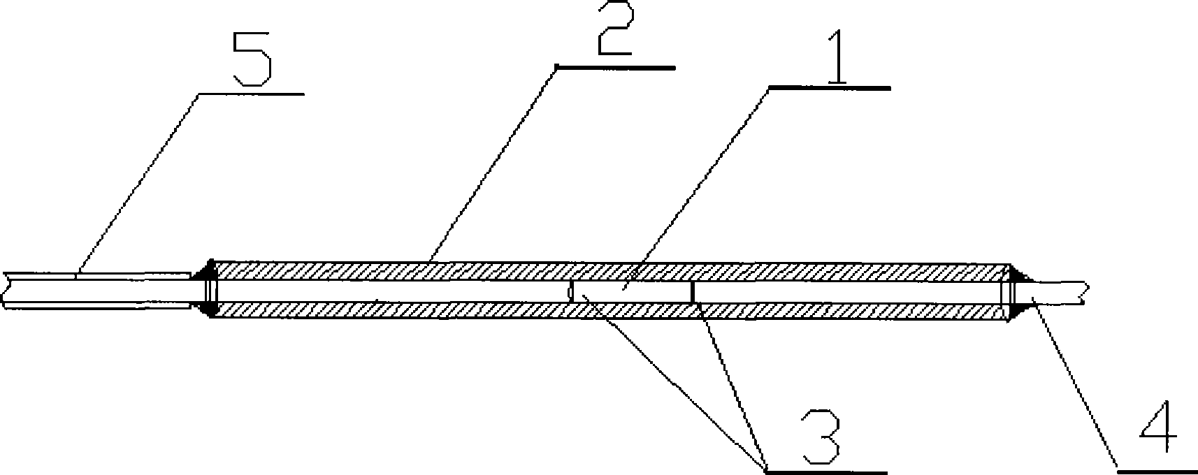
[0013] An aluminum metal capillary with an inner diameter of 0.13 mm and an outer diameter of 2 mm is placed in an ultrasonic bath filled with alcohol for cleaning and drying. Remove the coating layer at one end of the optical fiber. The bare optical fiber 4 is 5 to 10 mm longer than the aluminum metal capillary. Use acetone to clean the surface of the bare optical fiber 4. Then put the bare optical fiber 4 on the frame of the optical fiber cutter. The pinch plate on the side pushes the blade, which can form a score on the surface of the optical fiber, but the optical fiber cannot be interrupted during the operation. Insert the bare optical fiber 4 with a notch defect into the aluminum metal capillary 2, adjust the position of the notch defect in the aluminum metal capillary 2, and then use epoxy resin adhesive to connect the free end of the op...


PUM


Abstract

The invention discloses a method for manufacturing a sensitized extrinsic F-P optical fiber temperature sensor, which belongs to the technical field of a sensor. The method is characterized by comprising the following steps that: deficiency is generated by carving, and a flat end surface of an optical fiber is formed by tensing carved deficiency and using the characteristic that stress on the carved deficiency is concentrated; and a metal capillary tube and a bare optical fiber of an extrinsic F-P interface cavity are bonded together by a bonding agent, and the sensitized extrinsic F-P optical fiber temperature sensor is formed by two optical flat end surfaces and the metal capillary tube which has thermal expansion coefficients more than those of a glass capillary tube. The method has the advantages that the sensitized extrinsic F-P optical fiber temperature sensor which has excellent optical end surface and has no impurities in the interference cavity can be obtained, has fast temperature response, high temperature sensitivity, small volume, simple structure, high reliability, flexible manufacture, and the like, and can be used for high accuracy temperature measurement in strong electromagnetic radiating, inflammable and explosive and other situations.

Description

technical field [0001] The invention belongs to the technical field of sensors, and relates to a manufacturing method of an optical fiber temperature sensor, in particular to a manufacturing method of a sensitive extrinsic F-P optical fiber temperature sensor. Background technique [0002] The non-electrical thermometer commonly used in temperature measurement is a mercury thermometer, and the measurement result is stable, but it cannot automatically record data by computer. Electronic temperature sensors can flexibly realize temperature measurement and control, and are widely used in various industrial control equipment and electronic instruments: thermocouples can achieve high temperature measurement, but the accuracy is not high, and the measurement is inaccurate when the cold junction compensation is not good; Platinum resistors have high measurement accuracy, but low measurement sensitivity, and the measurement results are inaccurate when the wire compensation is not go...

Claims


Application Information

Patent Timeline
IPC IPC(8): G01K11/32G02B6/36
Inventor 王晓娜宋世德于清旭
Owner DALIAN UNIV OF TECH
Why Eureka
Try Eureka