Capillary array analyzer by rotating scanning

A capillary array and capillary technology, applied in the field of biological analysis, can solve the problems of limited instrument detection sensitivity, small fluorescence collection angle, and large working distance of the lens, and achieve the effect of low working distance requirements, small scanning inertia, and compact results

Inactive Publication Date: 2009-07-29
ZHEJIANG UNIV
View PDF0 Cites 6 Cited by
  • Summary
  • Abstract
  • Description
  • Claims
  • Application Information

AI Technical Summary

Problems solved by technology

In this way, the capillaries need to be arranged in a circle, the system volume is large, and the lens size is required to be small, and because the lens is located inside the cylindrical surface of the capillary array, the arrangement of the capillary array is concave to the lens, and the cylindrical surface of the array is limited by volume
Therefore, the working distance of the lens is required to be large, the angle of fluorescence collection is small, and the detection sensitivity of the instrument is limited.

Method used


Image

  • Capillary array analyzer by rotating scanning
  • Capillary array analyzer by rotating scanning
  • Capillary array analyzer by rotating scanning

Examples


Embodiment 1

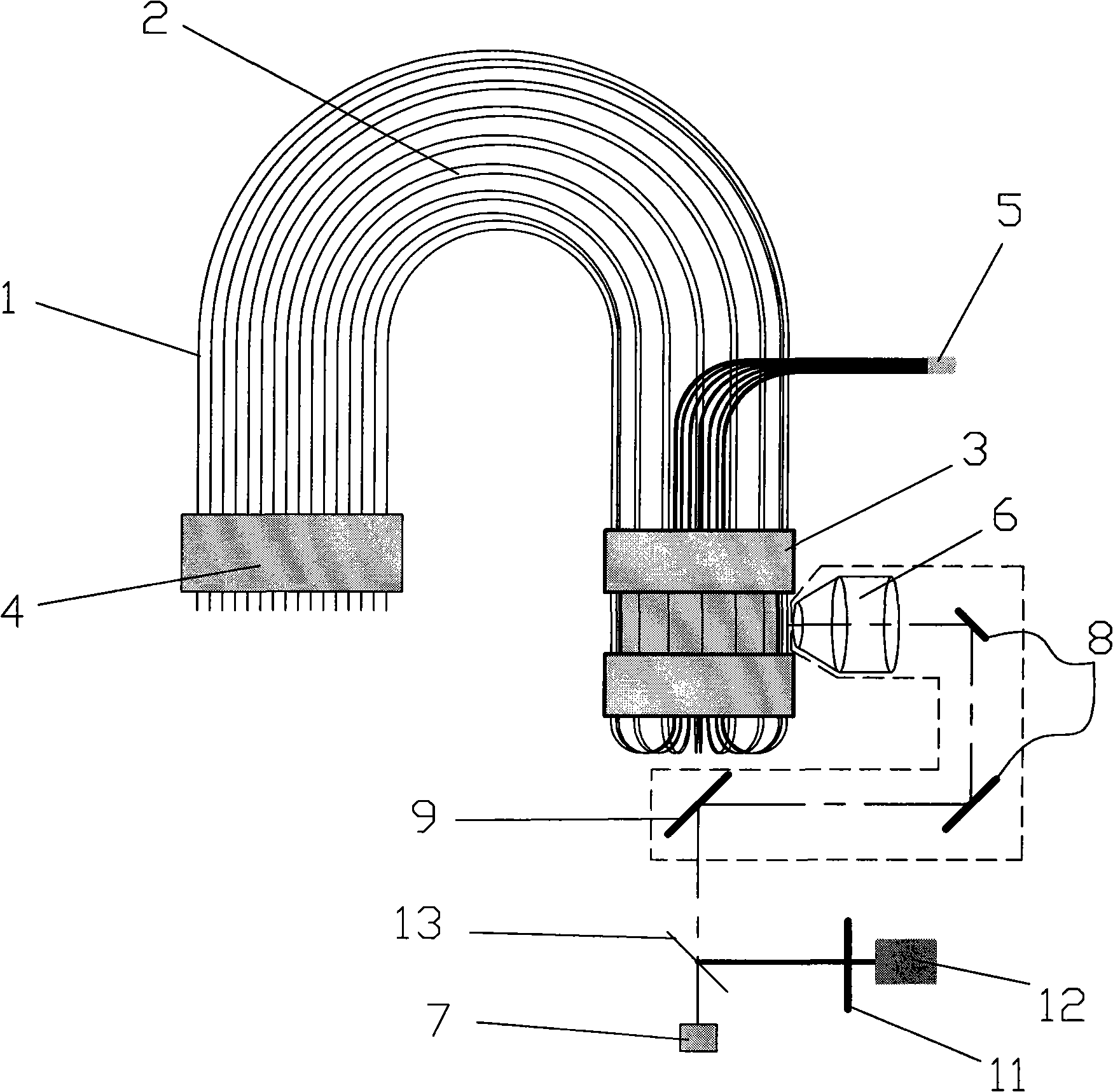
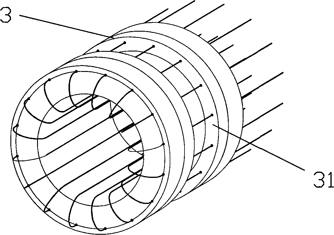
[0025] Embodiment one: if figure 1 , 2 As shown, the rotating scanning capillary array analyzer includes a capillary detection window fixing device 3, a capillary sampling end 4, a capillary waste liquid end 5, a scanning objective lens 6, a laser light source 7, a beam turning system 8, a scanning mirror 9, and a fluorescence beam splitter 10. Fluorescent color filter 11, photodetector 12, and scanning central axis 13. A plurality of capillary tubes 1 are arranged in a cylindrical array around the scanning central axis 13 to form a capillary array 2, which is fixed on the capillary detection window fixing device 3. The scanning objective lens 6 , the beam deflection system 8 and the scanning mirror 9 are mounted on the same scanning platform and rotate around the scanning central axis 13 to scan the detection window 31 on each capillary in the detection capillary array 2 . The fluorescence beam splitter 10 adopts a dichroic mirror or a mirror with a hole in the center.

[0...

Embodiment 2

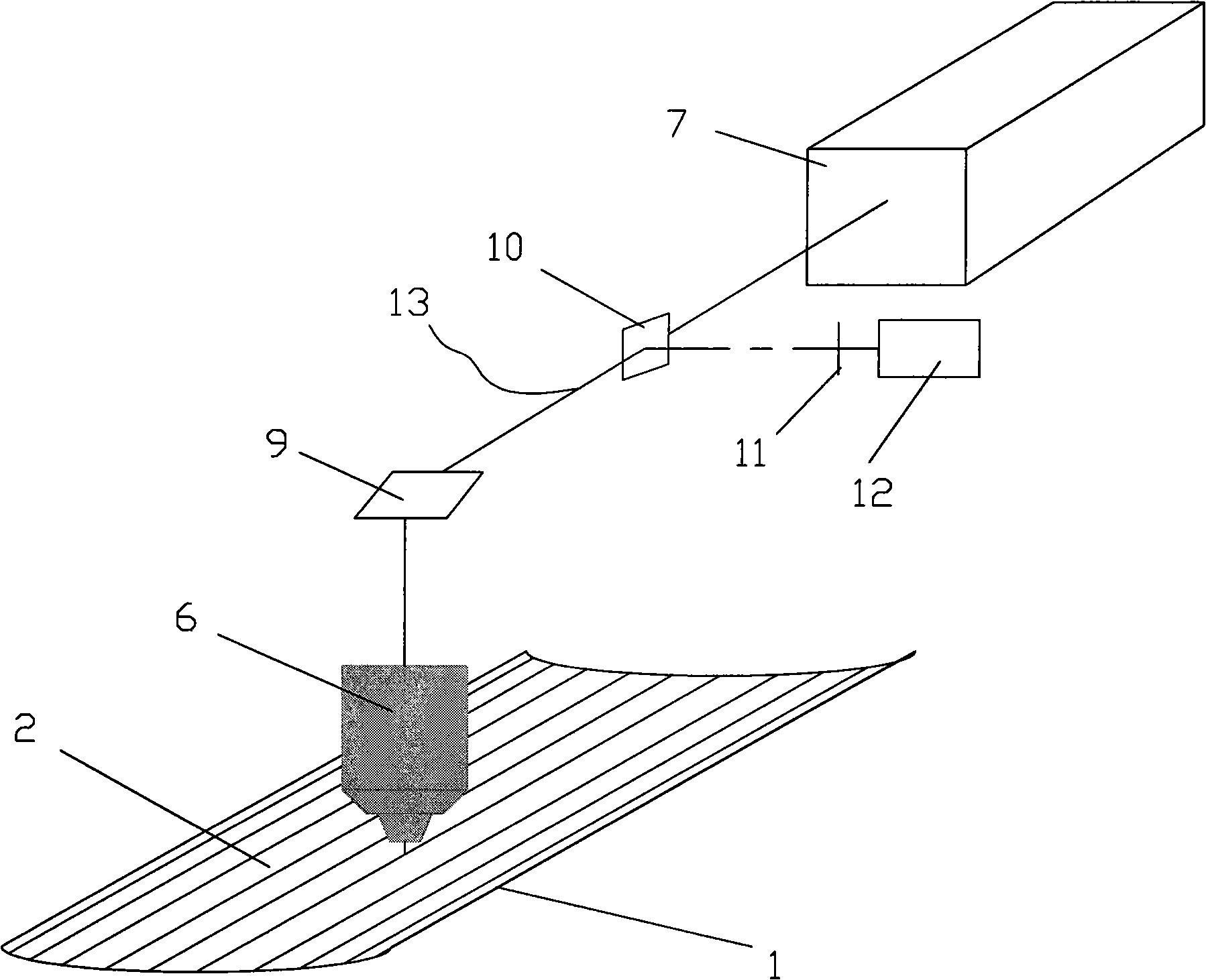
[0030] Embodiment two: if image 3 As shown, the capillary array 2 of this embodiment is an array formed by a plurality of capillaries 1 arranged on an arc surface around the scanning central axis 13 , and the scanning objective lens 6 and the scanning central axis 13 are located on the same side of the capillary array 2 .

[0031] The scanning objective lens 6 and the scanning mirror 9 are used to reciprocate and scan around the scanning central axis 13, and the capillary array 2 is fixed. During the scanning process, the central axis of the excitation beam coincident with the scanning central axis 13 is reflected by the mirror and meets the scanning objective lens 6. The optical axes coincide, and the signal fluorescence collected by the scanning objective lens 6 is reflected by the mirror and parallel to the scanning central axis 13, so as to avoid the movement of other optical devices of the detection system.

[0032] Other content of this embodiment is the same as that of...

Embodiment 3

[0034] Embodiment three: as Figure 4 As shown, the scanning objective lens 6 and the scanning central axis 13 are located on both sides of the capillary array 2, and the capillary array 2 is rotated to scan, and only the capillary array 2 needs to scan and detect around the scanning central axis 13, while other components do not move.

[0035] Other contents of this embodiment are the same as those of Embodiment 2.


PUM


Abstract

The invention belongs to the bioanalysis technical field, and relates to a rotational scanning capillary array analyzer. The analyzer comprises a laser light source, a scanning reflector, a scanning objective, a detection window fixing device, a capillary sampling end, a capillary exhaust liquid end, a light beam steering system, a fluorescence spectroscope, a fluorescence color filter, an optical detector and a scanning central shaft, wherein, a plurality of capillaries are arranged around the scanning central shaft to form a cylindrical array, and the capillary array is fixedly arranged in the detection window fixing device; laser beam of the light source sequentially passes through the fluorescence spectroscope, the scanning reflector, the light beam steering system and the scanning objective, and the scanning objective converges the laser beam on the detection window; a biological sample marked with fluorescence in the capillary is activated by the laser, irradiated fluorescence passes through the scanning objective, the light beam steering system, the fluorescence spectroscope and the fluorescence color filter, and is detected by the optical detector. The rotational scanning capillary array analyzer has the advantages of high flux, high sensitivity, large fluorescence collection angle and good performance.

Description

technical field [0001] The invention belongs to the technical field of biological analysis, in particular to a rotary scanning capillary array analyzer. Background technique [0002] Capillary electrophoresis is under the action of an electric field, the sample migrates in the capillary, and different components in the sample have different migration speeds to achieve separation, and detect at the detection window in the capillary, and analyze the sample through the detected signal. This technology is widely used in biochemical analysis, such as DNA and protein separation and analysis. It has high separation efficiency, low sample consumption and easy automation. It is widely used in DNA sequencing, biological and clinical research, forensic identification, environmental protection, analytical chemistry and food. It has a wide range of applications in detection and other fields. The detection of electrophoretic samples mainly includes isotope labeling, chemiluminescence met...

Claims


Application Information

Patent Timeline
Patent Type & Authority Applications(China)
IPC IPC(8): G01N21/64G01N33/483B01D57/02
Inventor 石岩王立强严惠民陆祖康
Owner ZHEJIANG UNIV
Why Eureka
Try Eureka