Pressure reducing air inlet high compression ratio internal-combustion engines

A high compression ratio, internal combustion engine technology, applied to internal combustion piston engines, combustion engines, mechanical equipment, etc., can solve problems such as damage to spark plug insulators, increased fuel consumption, engine overheating, etc. Energy saving effect

Inactive Publication Date: 2009-08-05
周同庆
View PDF0 Cites 5 Cited by
  • Summary
  • Abstract
  • Description
  • Claims
  • Application Information

AI Technical Summary

Problems solved by technology

At the same time, it will also cause a series of adverse consequences such as engine overheating, power drop, and fuel consumption increase.
Severe deflagration may even cause valve burnout, bearing bush rupture, spark plug insulator breakdown and other mechanical damage.

Method used


Image

  • Pressure reducing air inlet high compression ratio internal-combustion engines
  • Pressure reducing air inlet high compression ratio internal-combustion engines
  • Pressure reducing air inlet high compression ratio internal-combustion engines

Examples


no. 1 example

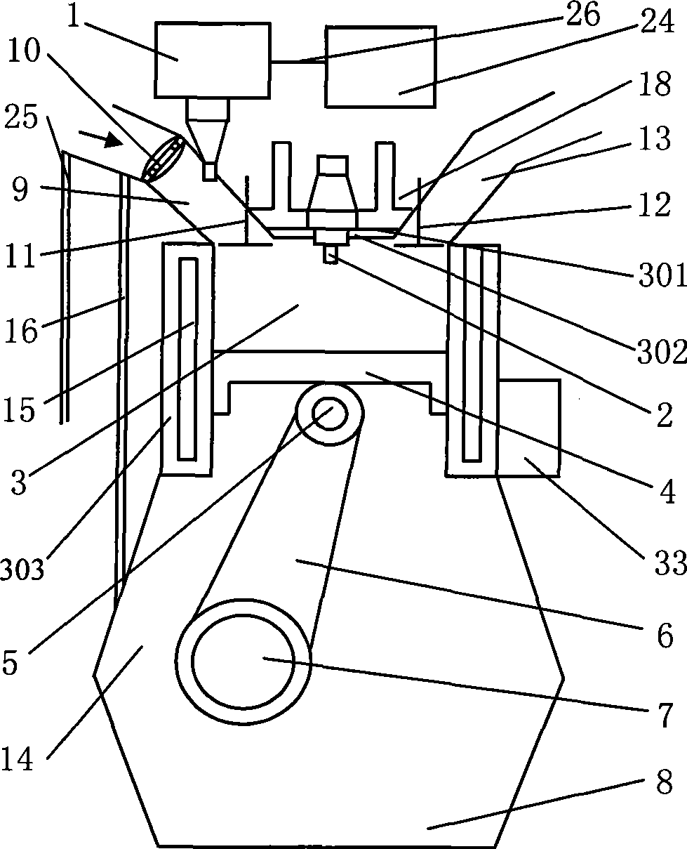
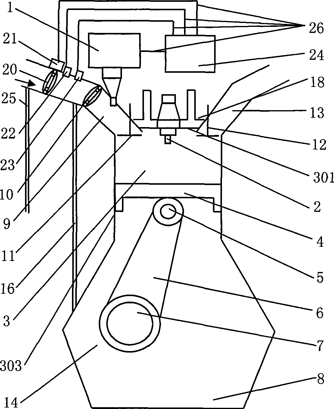
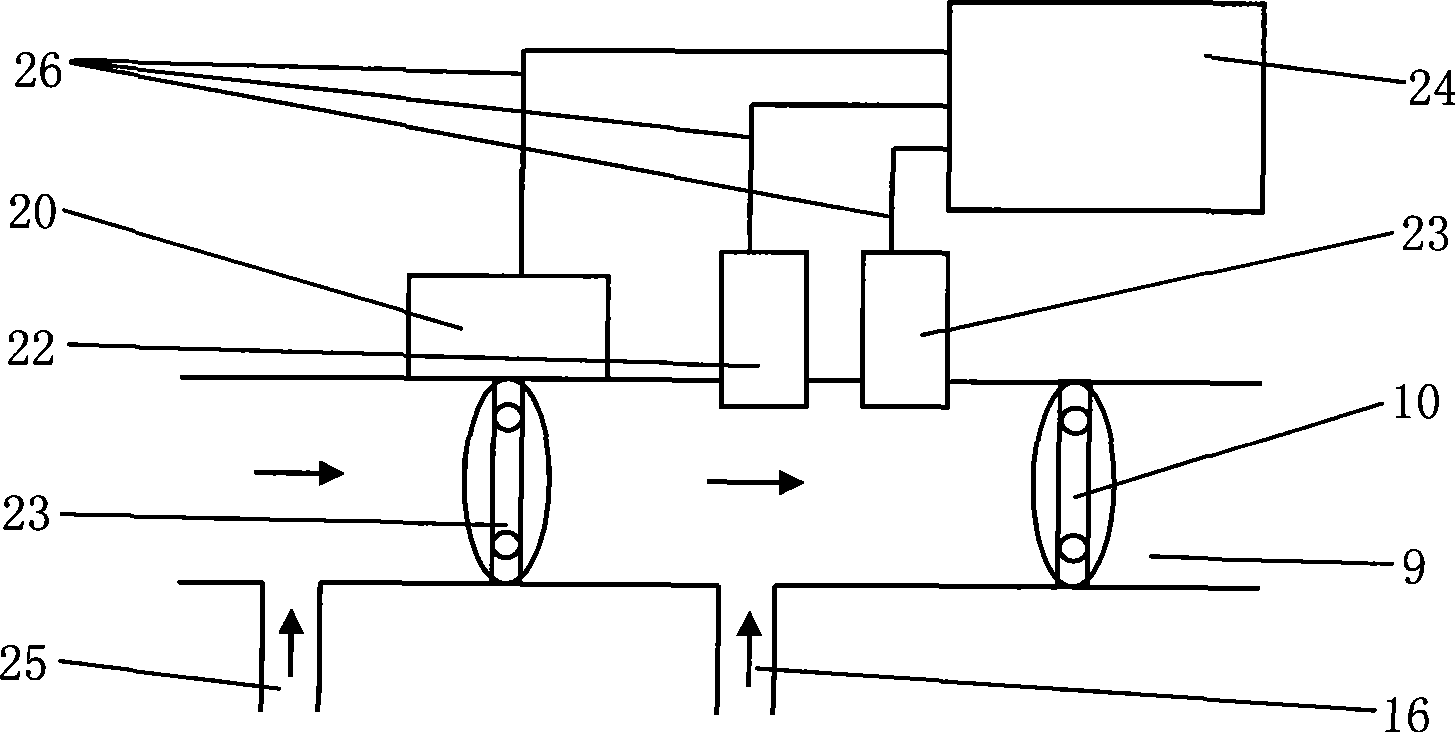
[0022] see figure 2 , image 3 . A decompression intake air high compression ratio internal combustion engine, comprising a fuel injection system 1, a spark plug 2, a cylinder 3, a piston 4, a piston pin 5, a connecting rod 6, a crankshaft 7, an oil pan 8, an intake manifold 9, and a throttle valve 10. Intake valve 11, exhaust valve 12, exhaust pipe 13 and crankcase 14, cylinder head 301 is arranged on the top of cylinder 3, oil pan 18 is arranged on cylinder head 301, cylinder block 303 is around cylinder 3, the The internal combustion engine also includes an intake pressure reducing valve 20 and its valve driver 21, a pressure sensor 22 and a flow sensor 23. The intake pressure reducing valve 20 is arranged on the intake manifold 9 and is located at the end of the throttle valve 10 in the intake direction. The upstream position, and the intake pressure reducing valve 20 is located between the crankcase suction passage 16 and the exhaust gas recirculation passage 25; the v...

no. 2 example

[0026] see Figure 4. A decompression intake high compression ratio internal combustion engine, comprising a fuel injection system 1, a spark plug 2, a cylinder 3, a piston 4, a piston pin 5, a connecting rod 6, a crankshaft 7, an oil pan 8, an intake manifold 10, an intake Door 11, exhaust valve 12, exhaust pipe 13 and crankcase 14, cylinder head 301 is arranged on the top of cylinder 3, and oil pan 18 is arranged on cylinder head 301, and this internal combustion engine also includes an intake pressure reducing valve 20 and its valve Driver 21 , pressure sensor 22 and flow sensor 23 . The intake decompression valve 20 is arranged on the intake manifold 9 and is located upstream of the throttle valve 10 in the intake direction, and the intake decompression valve 20 is located between the crankcase extraction passage 16 and the exhaust gas recirculation passage 25 The position between; the valve driver 21 is arranged on the outside of the intake manifold 9 near the position ...


PUM


Abstract

The invention relates to a four-stroke gasoline engine, in particular to a decompressed gas-intake internal combustion engine with high compression ratio, belonging to an engine. The decompressed gas-intake internal combustion engine with high compression ratio comprises an oil spout system, a spark plug, an gas cylinder, a piston, a piston pin, a connecting bar, a crank, an oil bottom shell, an intake pipe, an intake valve, an exhaust valve, an exhaust pipe and a crank case and also comprises a gas-intake decompressed valve, a valve drive of the gas-intake decompressed valve, an air pressure sensor and a flow sensor which are all arranged on the upper part of a motion valve and an extract opening of the crank case along a gas-intake direction to be used for restricting gas-intake quantity; the decompressed gas-intake internal combustion engine is improved in compression ratio and can not generate abnormal combustion such as deflagration, surface ignition, and the like. In addition, the decompressed gas-intake internal combustion engine with high compression ratio saves a water cooling system for a prior internal combustion engine. The invention reduces the exhaust emission, saves the energy, and also simplifies the structure of an internal combustion engine, decreases the part number and lowers the production cost on the basis of enhancing the heat efficiency of the internal combustion engine.

Description

technical field [0001] The invention relates to an internal combustion engine, especially a four-stroke gasoline engine. Background technique [0002] At present, most of the existing internal combustion engines, especially gasoline engines, adopt atmospheric air intake, that is, the intake air pressure is one atmospheric pressure. There is also a part of the internal combustion engine that uses supercharged air intake. The purpose of supercharged air intake is to increase the power per liter, that is, to increase the amount of work per unit volume by using more oil and gas to do more work. However, the thermal efficiency of gasoline engines with atmospheric air intake and supercharged air intake is generally low, the general level is only 28-45%, and the exhaust temperature is as high as 900-1200K. A large part of the energy of fuel combustion is discharged as heat. In addition, there are three One-tenth of the energy is conducted to the cooling system of the internal comb...

Claims


Application Information

Patent Timeline
Patent Type & Authority Applications(China)
IPC IPC(8): F02D9/02F02D9/08F02F1/10F02F1/00F02F1/24F02F3/10
CPCY02T10/14Y02T10/12
Inventor 周同庆
Owner 周同庆
Why Eureka
Try Eureka