Optical fiber coupling outputting vertical cavity surface emitting semiconductor laser device

A technology of vertical cavity surface emission and fiber coupling, which is applied to semiconductor lasers, structural details of semiconductor lasers, lasers, etc., to achieve the effects of low cost, stable power, and simple equipment and components

Inactive Publication Date: 2009-08-05
SHANGHAI INST OF OPTICS & FINE MECHANICS CHINESE ACAD OF SCI
View PDF0 Cites 9 Cited by
  • Summary
  • Abstract
  • Description
  • Claims
  • Application Information

AI Technical Summary

Problems solved by technology

Since the polarization state of the output light also depends on the phase difference, the disadvantage of this scheme still needs to control and fix the cavity length

Method used


Image

  • Optical fiber coupling outputting vertical cavity surface emitting semiconductor laser device
  • Optical fiber coupling outputting vertical cavity surface emitting semiconductor laser device
  • Optical fiber coupling outputting vertical cavity surface emitting semiconductor laser device

Examples


Embodiment 1

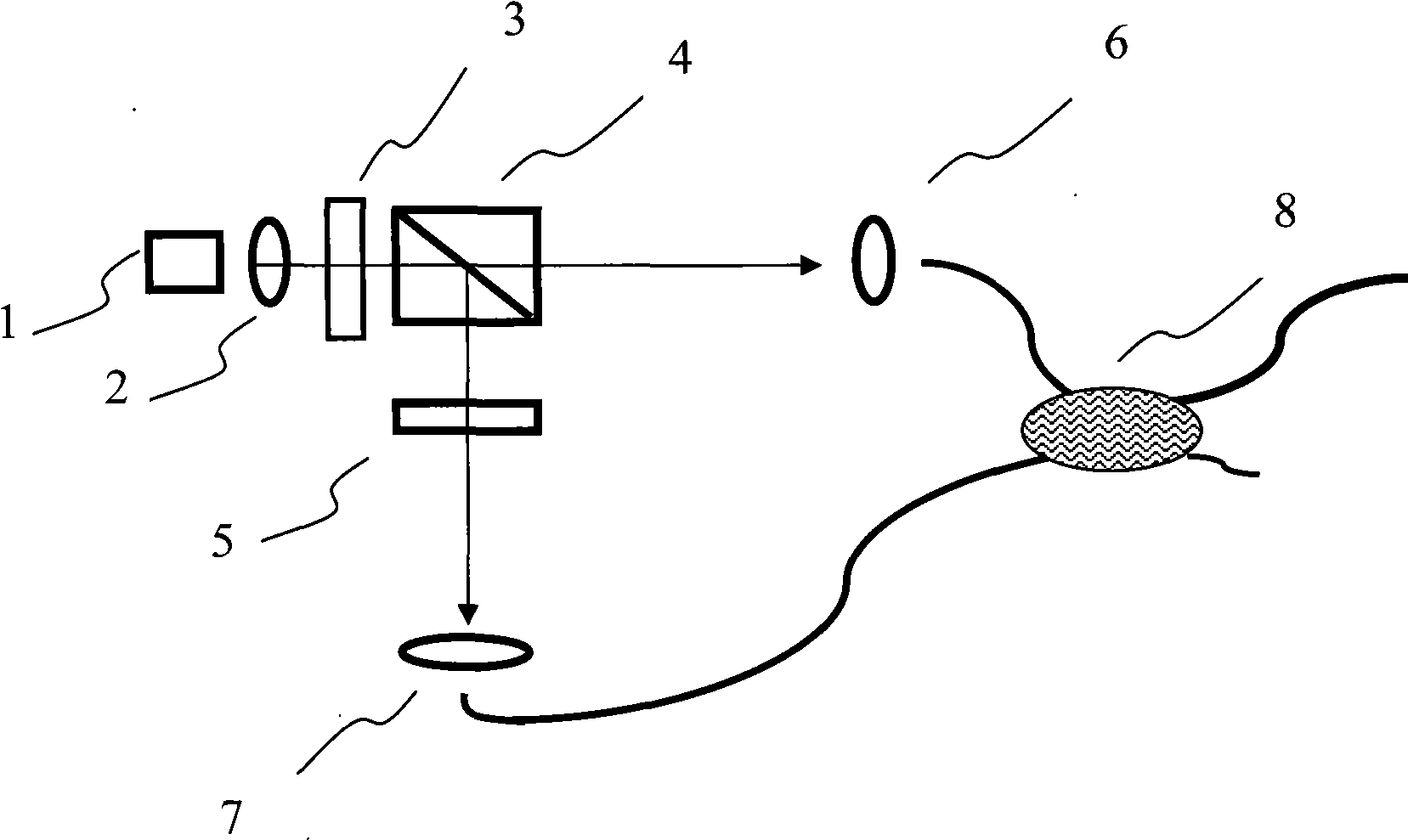
[0025] The working process of embodiment 1 is as follows (illustrate with the system requirement output p light as example, if require to output s light, whole process and p light output are corresponding): the semiconductor laser 1 output by vertical cavity surface emission contains p light and The light of the s-light component becomes parallel light through the collimating lens 2, rotates the direction of the first half-wave plate 3 to make it match the optical axis of the polarization beam splitter prism 4, and passes through the p-light of the polarization beam splitter prism 4 forward, The s light is reflected downward by the polarization beam splitter prism 4 , and the p light is coupled to the input fiber of the coupler 8 through the first coupling lens 6 and enters the coupler 8 . Described s light is reflected downwards through polarization beam splitter prism 4, and the optical axis of described second half-wave plate 5 and the polarization direction of s light becom...

Embodiment 2

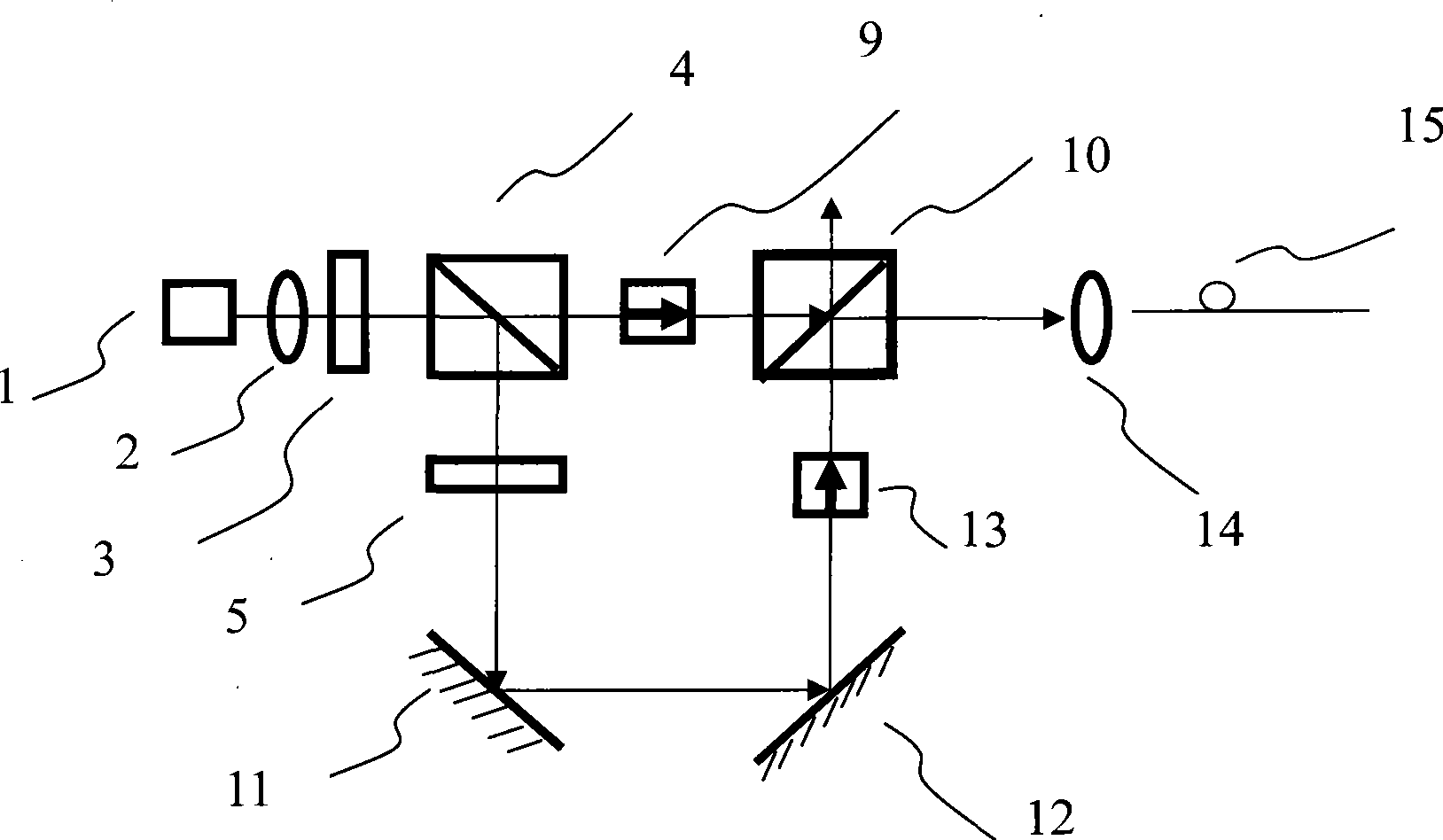
[0027] The working process of embodiment 2 is as follows (illustrate with the example that the system requires the output of p light, if the output of s light is required, the whole process corresponds to the output of p light): the output of the semiconductor laser 1 output by the vertical cavity surface contains p light and The light of the s-light component becomes parallel light through the collimating lens 2, and the light of the two polarization directions is rotated by the first half-wave plate 3, so that it matches the optical axis of the polarization beam splitting prism 4, and passes through the polarization beam splitting prism 4 After the p light passes through the front, the s light is reflected downward, the optical axis of the second half-wave plate 5 is 45° to the polarization direction of the s light, and the s light becomes p light after passing through the second half wave plate 5, and passes through the second half wave plate 5 Reflections from the first ref...


PUM


Abstract

The invention relates to a fiber coupling output and vertical-cavity surface-emitting semiconductor laser, which comprises a vertical-cavity surface-emitting semiconductor laser. A collimating lens, a first half-wave plate and a polarization beam splitting prism are arranged in sequence along the output light direction of the vertical-cavity surface-emitting semiconductor laser; the polarization beam splitting prism splits the output light of the vertical-cavity surface-emitting semiconductor laser into p polarized light and s polarized light; the polarization state of the p polarized light is maintained; the s polarized light is transformed into p polarized light; and the two paths of p polarized light are integrated and output, thereby realizing the stable single-polarization output. The semiconductor laser has the advantages of low cost, optical fiber coupling, high power and stable single-polarization output, and is applicable to the optical fiber communication, optical interconnection, optical fiber link, parallel optical signal processing and the like.

Description

technical field [0001] The invention relates to a vertical-cavity surface-emitting semiconductor laser, in particular to a fiber-coupled vertical-cavity surface-emitting semiconductor laser, which is suitable for occasions requiring high polarization stability and requiring fiber-coupled output. For example, optical fiber communication, optical interconnection, optical fiber link, and parallel optical signal processing. Background technique [0002] Compared with traditional edge-emitting lasers (EEL), vertical cavity surface-emitting semiconductor lasers (Vertica1-Cavity-Surface-EmittingLasers, hereinafter referred to as VCSEL) have many advantages: the volume of the resonator is small, and it is easy to produce microcavity effects. In a wide temperature and current range, it can realize dynamic single longitudinal mode operation, high dynamic modulation frequency, low power consumption, circular cross-section outgoing light, easy to form a two-dimensional array, suitable f...

Claims


Application Information

Patent Timeline
Patent Type & Authority Applications(China)
IPC IPC(8): H01S5/183H01S5/068G02B6/32G02B6/34H01S5/02
Inventor 沈力辛国锋陈高庭方祖捷瞿荣辉
Owner SHANGHAI INST OF OPTICS & FINE MECHANICS CHINESE ACAD OF SCI
Why Eureka
Try Eureka