Novel LED and a high-power radiator of a radiating element

A heat dissipation device and high-power technology, which is applied in the field of heat dissipation of high-power heat dissipation devices, can solve the problems of limited heat dissipation space, large equivalent thermal resistance, and difficulty in increasing the heat dissipation of the device, and overcome the problems of small contact area, small equivalent thermal resistance of heat conduction, and The effect of improving heat transfer efficiency

Active Publication Date: 2009-08-26
GUANGWEI HETONG ENERGY TECH BEIJING CO LTD
View PDF0 Cites 22 Cited by
  • Summary
  • Abstract
  • Description
  • Claims
  • Application Information

AI Technical Summary

Problems solved by technology

The second difficulty is that after the integration of the device is improved, the heat dissipation space that can be left for the device is also greatly limited, and the technical solutions that can be adopted are limited, which adds to the difficulty
Since electronic devices mainly use semiconductor materials, the temperature resistance of the device is relatively weak. For example, for LED devices, when the temperature rises, the efficiency of the device decreases significantly, the life is shortened, and the color changes, especially when the temperature of the device node Above about 130°C, the device will be burned out
Generally, the liquid cooling system is large in size, and the liquid cooling technology itself has potential safety hazards. Once the liquid cooling system leaks, it will cause LED damage
The heat transfer efficiency of heat pipe technology is very high, but the manufacturing process of ordinary heat pipes is very complicated, and the contact area between ordinary heat pipes such as circular heat pipes and the heating surface of electronic equipment is very small, resulting in large equivalent thermal resistance, which greatly limits the application

Method used


Image

  • Novel LED and a high-power radiator of a radiating element
  • Novel LED and a high-power radiator of a radiating element
  • Novel LED and a high-power radiator of a radiating element

Examples


Embodiment Construction

[0027] The present invention will be described below in conjunction with the accompanying drawings.

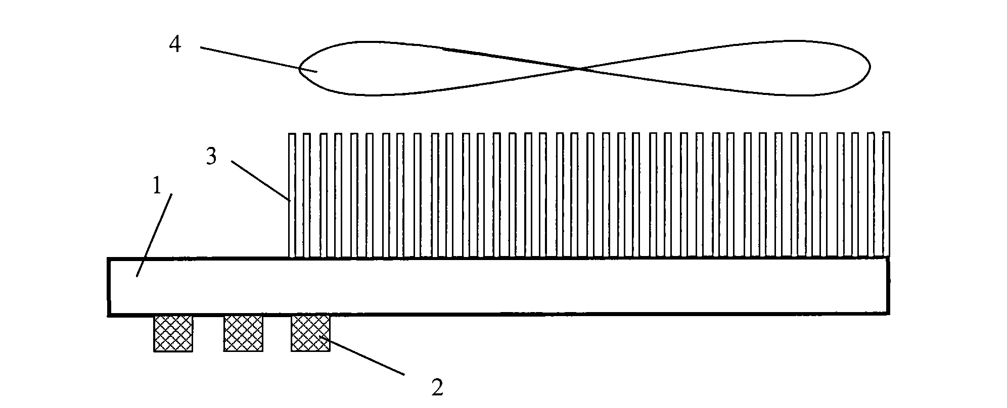
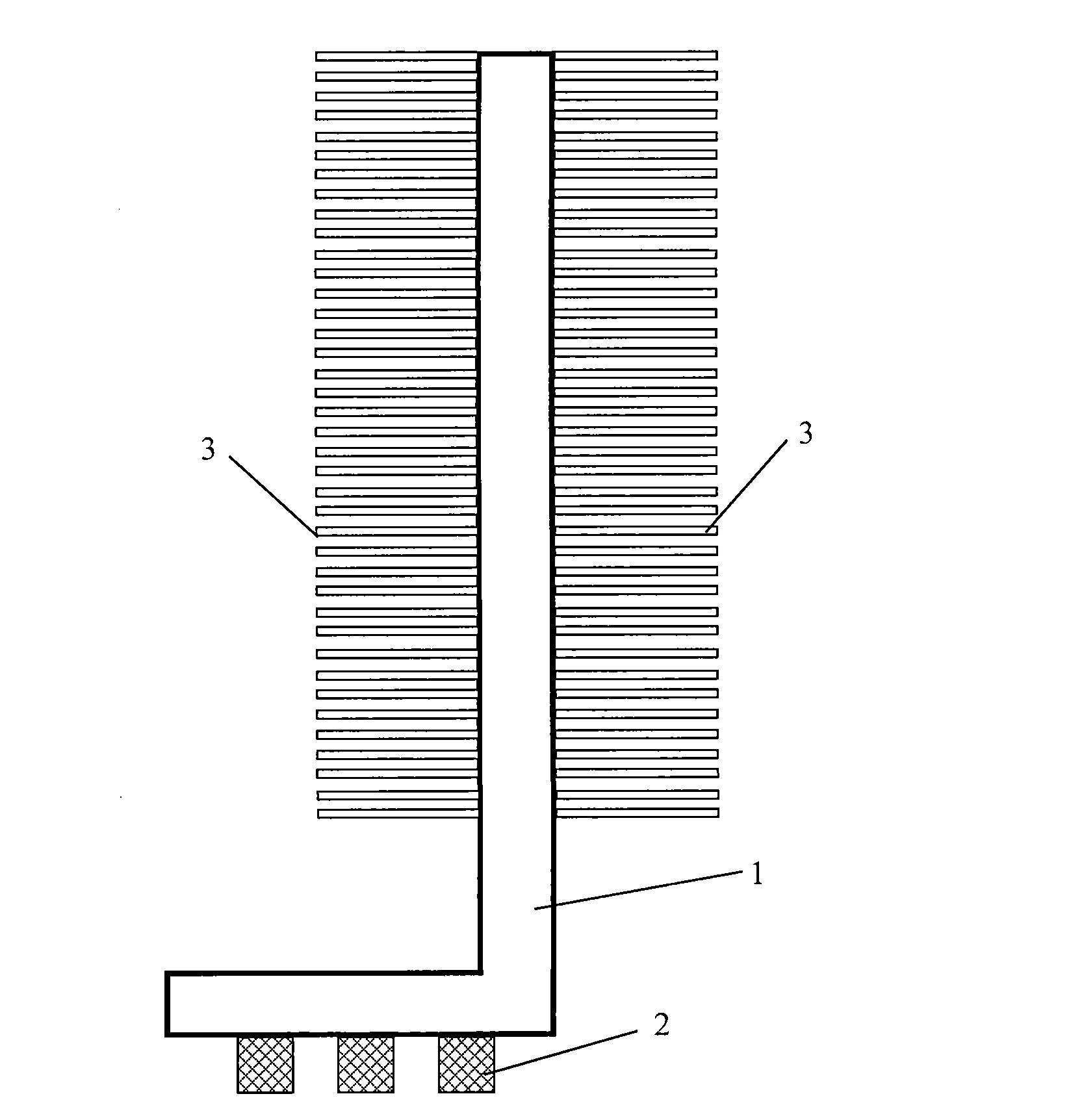
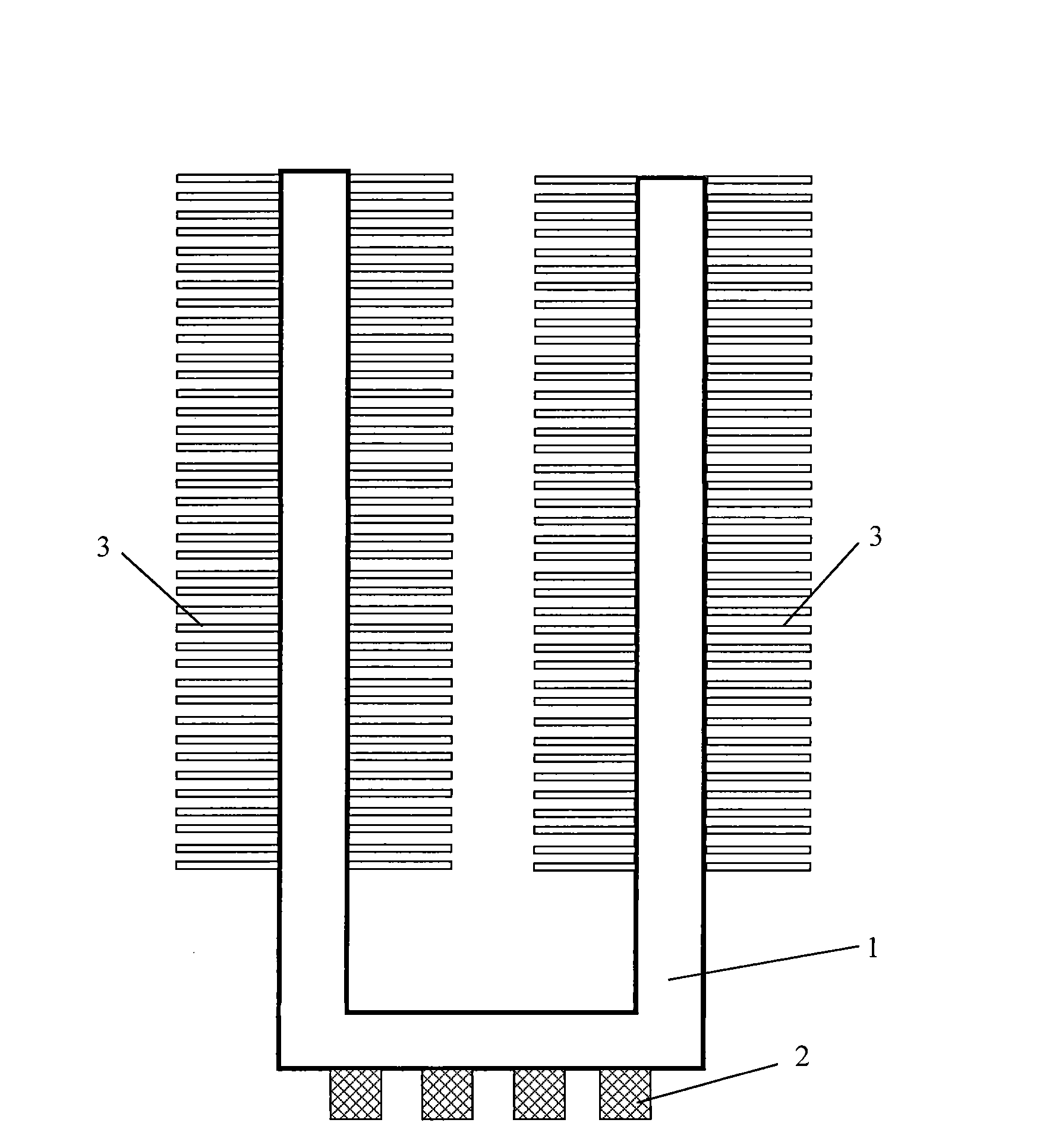
[0028] figure 1 It is a structural schematic diagram of the first preferred embodiment of the radiator of the new LED and high-power heat dissipation device of the present invention. The radiator of the novel LED and high-power heat dissipation device includes a flat heat pipe 1, and the flat heat pipe is a metal material that is extruded or stamped. Formed two or more through-hole array plate structures arranged side by side, taking into account the heating characteristics of the heating surface of LEDs and high-power heat dissipation devices, the structural characteristics of LED and high-power heat dissipation devices installation, and the influence of installation space and working environment factors, etc. The equivalent diameter of the through hole of a specific size is set based on various factors. For example, the operating temperature of the LED is usually within 120°...


PUM


Abstract

The invention relates to a novel LED and a high-power radiator of a radiating element, comprising flat plate heat pipes which are of two or more via-hole array flat plate structures arranged side by side; the via-hole array flat plate structures are formed by carrying out extrusion or punch forming on metal materials; the equivalent diameter of the via hole is 0.5-3mm; the via hole is filled with liquid propellant and both ends of the flat plate heat pipes are packaged by sealing; an evaporation section of the flat plate heat pipe contacts heating surfaces of the LED and the high-power radiating element and a condensation section thereof radiates through the radiating element. The novel LED and the high-power radiator of a radiating element overcome the disadvantages that the contact area of the existing circular heat pipes and the heating surfaces of the LED and the high-power radiating element is small, the equivalent resistance of heat conduction is large and the manufacturing process is complex, which have the advantages of high radiating efficiency and simple process.

Description

technical field [0001] The invention relates to a heat dissipation technology of a high-power heat dissipation device, in particular to a heat sink formed by a flat heat pipe for heat dissipation of an LED and a high-power heat dissipation device. Background technique [0002] With the rapid development of LED technology, the calorific value and heat flux density of LEDs have increased significantly. At present, the heat flux density of LED devices is as high as 400W / cm 2 . The general natural convection cooling heat flux density does not exceed 0.8W / cm 2 , the heat flux density of air-cooled heat dissipation does not exceed 10W / cm 2 , only by using liquid cooling and heat pipe technology can the heat flux density of heat dissipation reach 100W / cm 2 . Reaching and exceeding this heat flux density value is a worldwide problem in heat dissipation technology. The second difficulty is that after the device integration level increases, the heat dissipation space that can be ...

Claims


Application Information

Patent Timeline
Patent Type & Authority Applications(China)
IPC IPC(8): H01L23/427H01L23/367H01L33/00F28D15/04F28F1/24F28F21/08
Inventor 赵耀华张楷荣刁彦华
Owner GUANGWEI HETONG ENERGY TECH BEIJING CO LTD
Why Eureka
Try Eureka