Gas turbine

A gas turbine and combustion gas technology, which is applied in the direction of gas turbine devices, mechanical equipment, engine functions, etc., can solve the problems of reduced air for combustion, longer start-up time, and rise in combustion temperature, so as to suppress the increase of NOx emissions and suppress the output Inefficiency and the effect of suppressing pressure loss

Inactive Publication Date: 2009-08-26
MITSUBISHI HEAVY IND LTD
View PDF1 Cites 12 Cited by
  • Summary
  • Abstract
  • Description
  • Claims
  • Application Information

AI Technical Summary

Problems solved by technology

In the cooling device of the steam cooling method, since the burner is cooled by the steam generated by the exhaust heat recovery boiler, incidental equipment such as steam piping for circulating the steam between the gas turbine and the exhaust heat recovery boiler is required, resulting in a structural increase in size and complexity
In addition, in order to cool the gas turbine, it is necessary to start the exhaust heat recovery boiler, which complicates the operation control, and at this time, since the exhaust heat recovery boiler needs to be preheated, the start-up time becomes longer
Furthermore, since the combustor is cooled by steam, there is a problem that the gas turbine loses heat, resulting in low equipment efficiency
[0009] In an air-cooled cooling device, since the combustor is cooled by using a part of the compressed air compressed by the compressor, there is a problem that the combustion air decreases, the combustion temperature in the combustor rises, and the NOx in the exhaust gas increases.
In addition, in an ultra-high temperature gas turbine, since the temperature of the cylinder chamber rises to a high temperature, the cooling capacity of the cooling device of the air cooling method is low, and it is difficult to achieve cooling.
Furthermore, in the cooling device of the recovery air cooling method, although the combustor is cooled by the compressed air compressed by the compressor, the cooled compressed air is supplied to the combustor, and the low nitrogen can be achieved by ensuring the combustion air. However, since the compressed air is recovered after cooling the combustor wall, there is a problem that the pressure loss in the combustor is large and the efficiency of the turbine is low
In addition, since the flow channel sleeve needs to be provided on the outer peripheral side of the inner cylinder of the combustor, the structure becomes complicated due to the increase of structural parts.

Method used


Image

  • Gas turbine
  • Gas turbine
  • Gas turbine

Examples


Embodiment 1

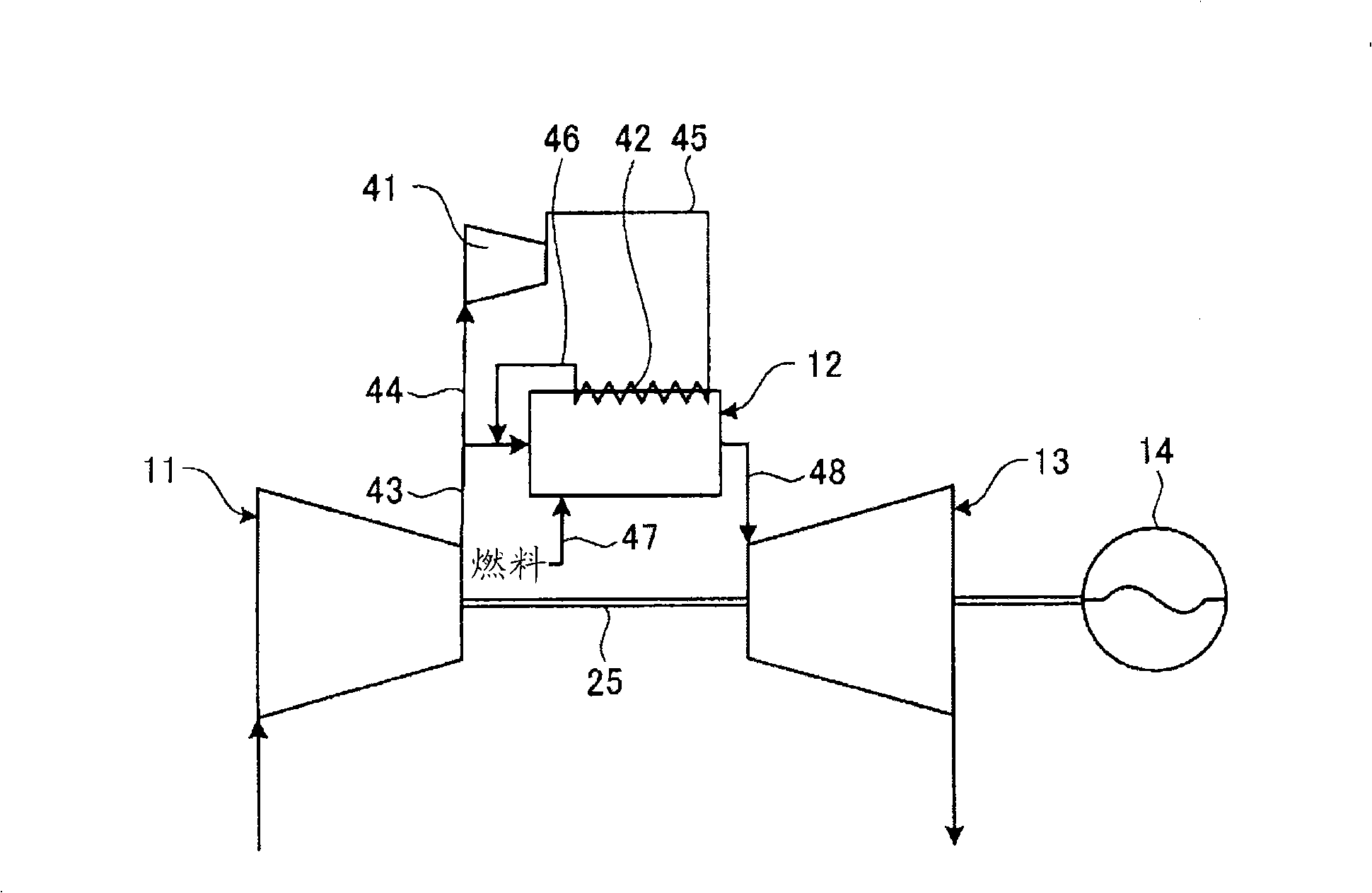
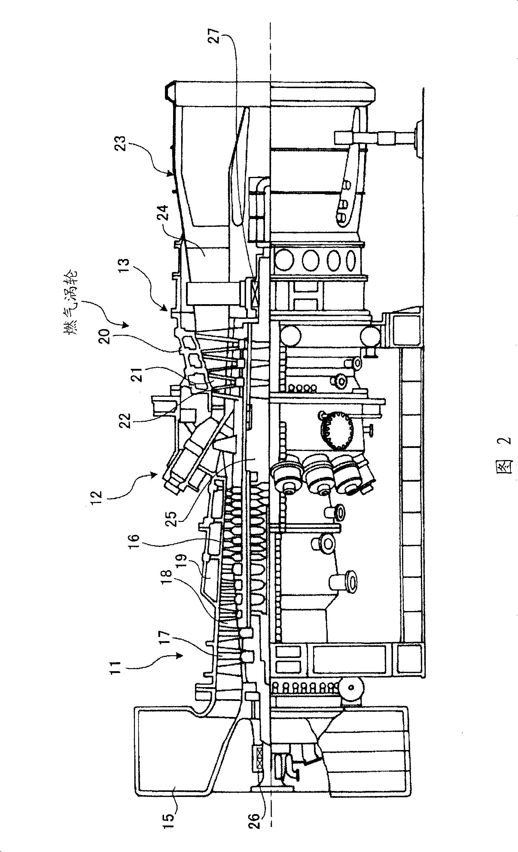
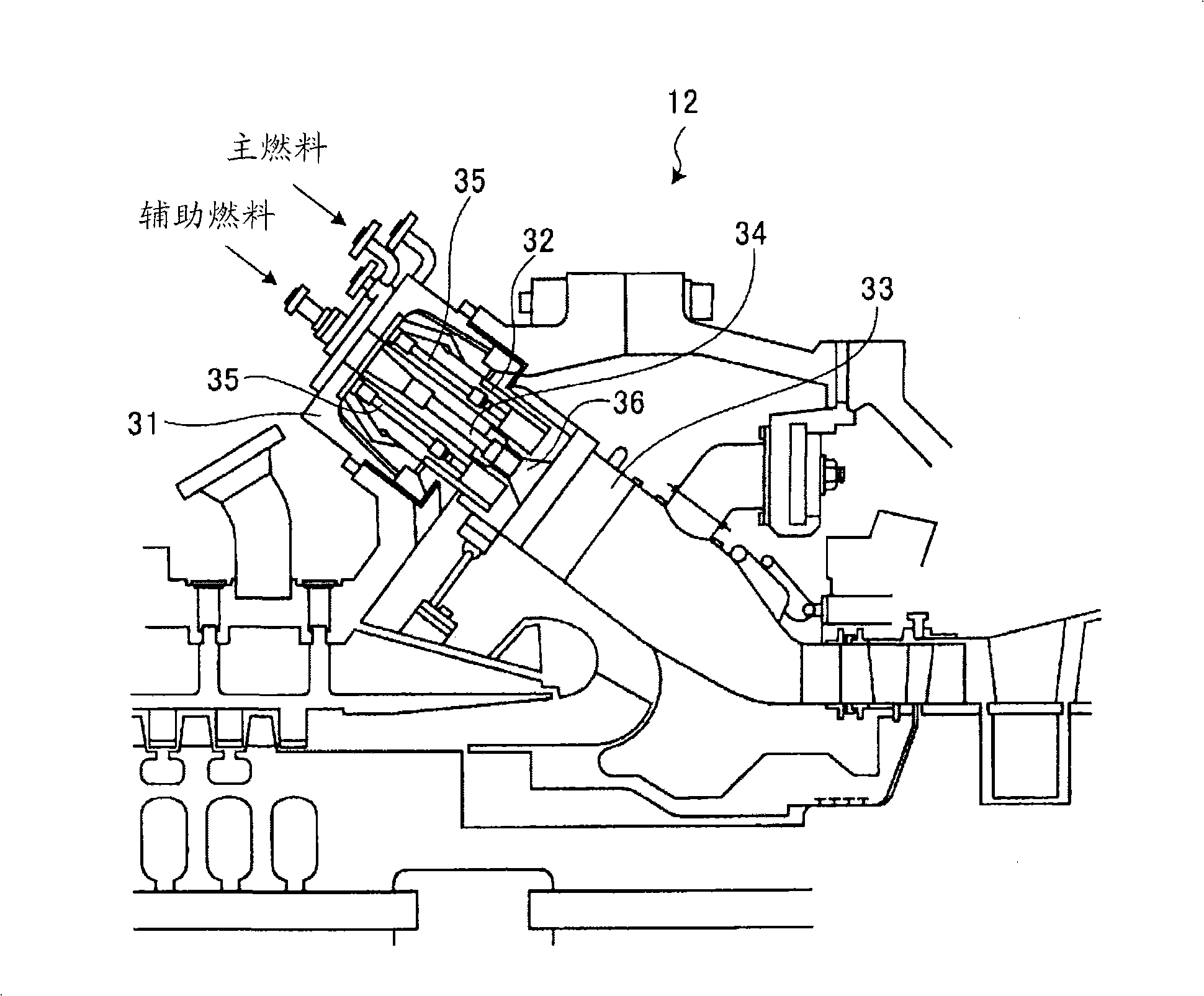
[0069] figure 1 is a schematic diagram showing a gas turbine according to Embodiment 1 of the present invention, figure 2 is a schematic configuration diagram showing the gas turbine of Embodiment 1, image 3 It is a schematic configuration diagram showing the combustor of the gas turbine of the first embodiment.

[0070] Such as figure 1 and figure 2 As shown, the gas turbine in Embodiment 1 is composed of a compressor 11 , a combustor 12 , and a turbine 13 , and a generator 14 is connected to the turbine 13 . The compressor 11 has an air inlet 15 for taking in air, and a plurality of fixed impellers 17 and moving impellers 18 are arranged alternately in a compressor cylinder chamber 16 , and an air extraction manifold 19 is provided outside the compressor cylinder chamber 16 . The combustor 12 supplies fuel to the compressed air compressed by the compressor 11, and ignites it with a torch to burn it. In the turbine 13 , a plurality of fixed impellers 21 and movable im...

Embodiment 2

[0084] Pic 4-1 is a schematic view showing a combustor cooling device for a gas turbine according to Embodiment 2 of the present invention, Figure 4-2 to Figure 4-4 It is a schematic diagram showing a modified example of the gas turbine combustor cooling device of the second embodiment. Components having the same functions as those already described in the above-mentioned embodiments are assigned the same reference numerals, and redundant descriptions are omitted.

[0085] Such as Pic 4-1 As shown, in the gas turbine of Embodiment 2, the combustor cooling device 51 is a plurality of cooling passages formed in the wall portion of the inner tube 52 constituting the combustor 12 . Specifically, in the combustor cooling device 51 , a plurality of cooling passages 53 are formed in the wall portion of the inner tube 52 along its longitudinal direction (flow direction of combustion gas). Further, an annular head 54 is fixed to the outer peripheral portion of the inner cylinder ...

Embodiment 3

[0096] Figure 5 is a schematic diagram showing a gas turbine according to Embodiment 3 of the present invention. Components having the same functions as those already described in the above-mentioned embodiments are assigned the same reference numerals, and redundant descriptions are omitted.

[0097] Such as Figure 5 As shown, in the gas turbine of Embodiment 3, the compressor 11 is connected to the combustor 12 via the compressed air supply line 43 , and is connected to the pressure booster 41 via the compressed air branch line 44 branching off from the compressed air supply line 43 , the pressure booster 41 is connected to the burner cooling device 42 via the cooling air supply line 45, the water supply line 71 is connected to the cooling air supply line 45, and the water injection device (moisture addition mechanism) is installed on the water supply line 71. )72. In addition, the combustor cooling device 42 is connected to the compressed air supply line 43 via the com...


PUM


Abstract

The invention provides a gas turbine, in which compressed air that is compressed by a compressor (11) is mixed with fuel in a combustor (12), the mixture is burned to produce combustion gas, and the combustion gas is provided to a turbine (13) to produce rotative power, includes: a pressurizing unit (41) that pressurizes some of the compressed air that is compressed by the compressor (11); a combustor cooling unit (42) that cools the combustor (12) with the compressed air that is pressurized by the pressurizing unit (41); and a compressed air circulation line (46) that provides the compressed air to the casing of the combustor (12). In the gas turbine, the combustor can be cooled by minimizing pressure loss of the compressed air, and degradation of the power efficiency can be prevented.

Description

technical field [0001] The present invention relates to a gas turbine that supplies fuel to compressed compressed air to combust it, and supplies the generated combustion gas to a turbine to obtain rotational power. Background technique [0002] A general gas turbine is composed of a compressor, a combustor, and a turbine. The air taken in from the air inlet is compressed by the compressor to become high-temperature and high-pressure compressed air. In the combustor, fuel is supplied to the compressed air and combusted. The high-temperature, high-pressure combustion gas drives a gas turbine, which in turn drives an electric generator connected to the turbine. [0003] In such a gas turbine, when the combustion temperature of the combustor becomes high, nitrogen oxides (NOx) in the exhaust gas increase, so a cooling device is provided in the combustor. Conventional cooling devices for combustors include steam cooling methods, air cooling methods, recovery air cooling methods...

Claims


Application Information

Patent Timeline
Patent Type & Authority Applications(China)
IPC IPC(8): F02C7/18F01K23/10F02C6/18F02C7/143F02C7/224
CPCF02C7/224F02C7/18Y02E20/16Y02E20/18F02C7/08F02C1/04F05D2260/205F01K23/10F02C6/18F02C7/143
Inventor 石黑达男田中克则小西哲
Owner MITSUBISHI HEAVY IND LTD
Why Eureka
Try Eureka