Sensing method and device for micro inner cavity size and three-dimensional coordinate based on two-dimensional micro-focus collimation

A technology of three-dimensional coordinates and sensing devices, applied in measurement devices, optical devices, instruments, etc., can solve the problems of increased data volume, difficulty in adjusting the imaging optical path, and difficulty in distinguishing the polarity of measurement elements, and achieves efficient extraction and system structure. Simple, easy to measure effects online

Inactive Publication Date: 2009-09-02
HARBIN INST OF TECH
View PDF0 Cites 42 Cited by
  • Summary
  • Abstract
  • Description
  • Claims
  • Application Information

AI Technical Summary

Problems solved by technology

The resolution of 4nm is obtained through two steps. The first step is optical imaging magnification with a magnification of 35 times. In this step, the diameter of the optical fiber measuring rod is generally between 20 μm and 125 μm. If the magnification is higher, a more complex imaging system design and a larger area of ​​the CCD receiver are required, which will cause the method to lose its practicability in the measurement application of tiny deep holes
The second step is to use the image algorithm for contour recognition to judge the displacement of the optical fiber measuring rod. The resolution of this step can only reach the sub-pixel level and it is difficult to greatly improve it.
Although this method obtains a higher resolution in the Z direction, the Z direction detection can only work alone, and cannot work simultaneously with the X and Y direction detection. The position of the plane perpendicular to the Z direction in the Z direction
[0010] 2. The detection system has no absolute "0" position in the measurement direction
The existing detection methods for tiny inner cavities mainly judge the displacement of the optical fiber measuring rod through the two-dimensional images received by the area array CCD. This method does not have an absolute "0" position, which makes it difficult for the detection system to distinguish the polarity of the measurement elements. , it is also difficult to obtain higher measurement repeatability
[0011] 3. The real-time performance of the detection system is poor, and it is difficult to achieve precise online measurement
The detection method adopted by the National Institute of Standards and Technology must use two-way area array CCD to receive signal images (B.Murali-krishnan, J.A.Stone, J.R.Stoup.Fiberdeflection probe for small hole metrology.Precision Engineering 30(2006)154-164.) , and since the magnification of the imaging optical path of the optical fiber measuring rod is only 35 times, a more complex image algorithm must be used to achieve high-resolution monitoring of the displacement of the optical fiber measuring rod, which leads to a large increase in the amount of data that the measurement system needs to process and reduces the detection rate. Due to the real-time performance of the system, it is difficult to realize the synchronization of aiming signaling, start and stop measurement in the process of small inner cavity size and three-dimensional coordinate measurement
[0012] 4. The structure to realize displacement sensing is relatively complicated
The detection method adopted by the National Institute of Standards and Technology must use two orthogonal optical fiber detection rod imaging optical paths to realize three-dimensional detection of the displacement of the optical fiber detection rod (B.Murali-krishnan, J.A.Stone, J.R.Stoup.Fiber deflection probe for small hole metrology. Precision Engineering 30(2006) 154-164.), which makes it difficult to adjust the imaging optical path. It is necessary to check the orthogonality of the two optical paths. The subsequent image signal processing of the two optical paths is also more complicated. Signal synchronization issues, which make this method unable to further improve work efficiency in terms of specific use and operation

Method used


Image

  • Sensing method and device for micro inner cavity size and three-dimensional coordinate based on two-dimensional micro-focus collimation
  • Sensing method and device for micro inner cavity size and three-dimensional coordinate based on two-dimensional micro-focus collimation
  • Sensing method and device for micro inner cavity size and three-dimensional coordinate based on two-dimensional micro-focus collimation

Examples


Embodiment Construction

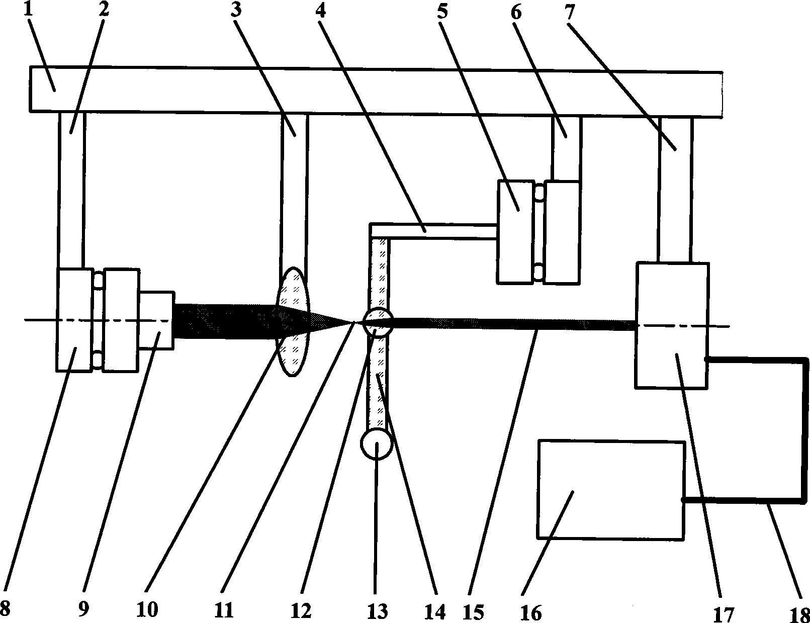
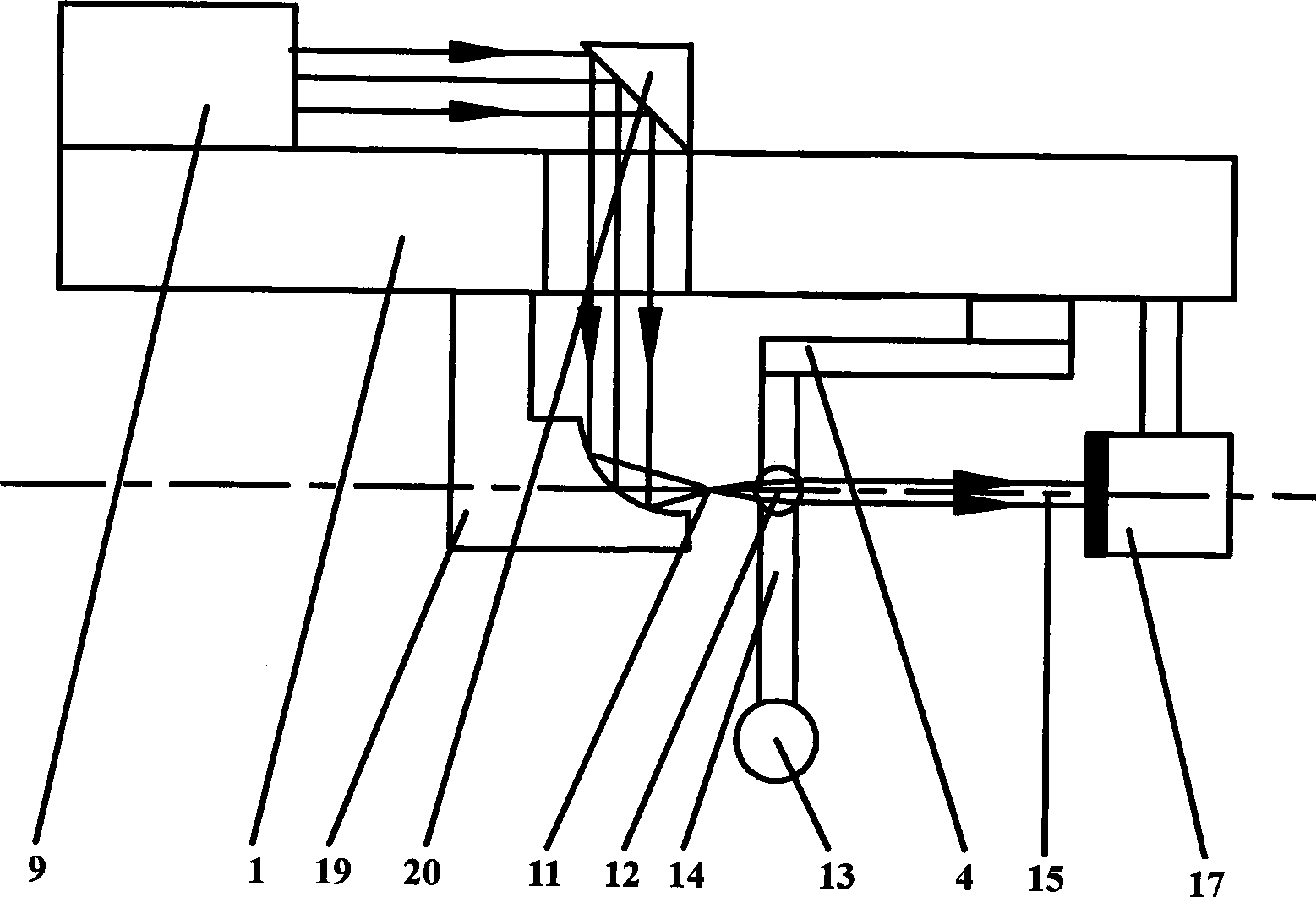
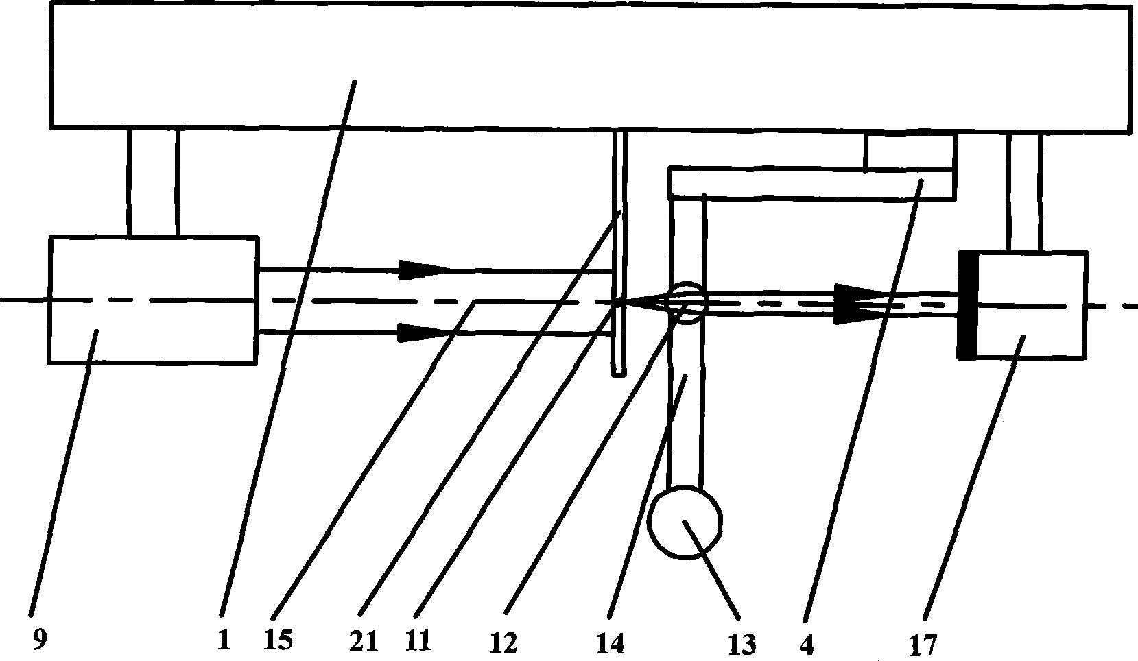
[0035] A micro-cavity size and three-dimensional coordinate sensing method based on two-dimensional micro-focus collimation, through the following steps to realize the sensing of the three-dimensional displacement of the optical fiber probe measuring rod:

[0036] ① Combining a part of the fiber optic probe rod with the microspherical biconvex lens;

[0037] Since the three-dimensional displacement monitoring of the optical fiber probe measuring rod 14 is to be realized by establishing a two-dimensional micro-focus collimated imaging optical path of a point light source, it is necessary to use a microspherical double-convex lens 12 with a small focal length in combination with the optical fiber probe measuring rod 11, so that They have the same motion state, and the spherical radius of the microspherical double-convex lens 12 is usually between 20 μm and 100 μm, so its curvature is 5×10 4 m -1 ~10 4 m -1 between. Optical fiber probe measuring rod 14 is a measuring rod usin...


PUM


Abstract

The invention relates to a sensing method and a device for micro inner cavity size and three-dimensional coordinate based on two-dimensional micro-focus collimation, belonging to the technical filed of precise instrument manufacture and measurement, in particular to a sensing method and a device for micro and complex inner cavity size and three-dimensional coordinate in the filed of sub-macroscopy, which is especially suitable for the three-dimensional detection of blind holes with large depth-diameter ratio. The device combines a micro spherical biconvex lens and an optical fiber probe measuring rod, and establishes a point light two-dimensional micro-focus collimation imaging light path by using the micro spherical biconvex lens, thereby realizing the high magnification and the sensing for the three-dimensional displacement of the optical fiber probe measuring rod by utilizing the light path. The invention has the characteristics of small measured force of a single optical fiber probe, easy miniaturization, large measured depth-diameter ratio, simple system structure, good real-time performance, easy practical application, and has obvious advantages for carrying out the quick and ultra-precise measurement and calibration for the inner cavity micro-size and the three-dimensional coordinate. Especially, the top of the resolution capability can reach the deep sub-nanometer magnitude, and an absolute zero position exists in the three-dimensional measurement direction.

Description

technical field [0001] The invention belongs to the technical field of precision instrument manufacturing and measurement, in particular to a sensing method and device for the structural dimensions and three-dimensional coordinates of tiny and complex inner cavities in the "sub-macroscopic" field, and is especially suitable for small blind holes with large depth-to-diameter ratios 3D structure size detection. Background technique [0002] One of the trends in the development of industrial products is the miniaturization and precision of the inner scale. With the development of the aerospace industry, the electronic industry, and medical equipment, the demand for precision and tiny inner cavity components has increased sharply, such as fuel injection pipes, inertial instruments, and optical fibers. Holes in ferrules, wire drawing dies, printed circuit boards and medical devices (such as Eustachian tubes), etc. Due to the limitation of the space scale and the influence of the...

Claims


Application Information

Patent Timeline
Patent Type & Authority Applications(China)
IPC IPC(8): G01B11/02G01B11/03
CPCG01B11/007
Inventor 谭久彬王飞崔继文
Owner HARBIN INST OF TECH
Why Eureka
Try Eureka