

Method for improving emission characteristic of film ZnO field
A field emission, thin film technology, applied in the field of field emission flat panel display, can solve the problems of high threshold voltage and low emission current density, and achieve the effect of reducing work function, reducing height and increasing field emission current density
Inactive Publication Date: 2010-11-10
IRICO
View PDF0 Cites 0 Cited by
- Summary
- Abstract
- Description
- Claims
- Application Information
AI Technical Summary
Problems solved by technology
However, the research on ZnO field emission cathode materials is currently mainly focused on one-dimensional nanomaterials prepared by chemical methods. There are few reports on the field emission properties of ZnO thin films prepared by physical methods such as magnetron sputtering. The reason is that although thin film ZnO is used as an electron emitter body, good emission uniformity, high stability, strong adhesion to the substrate, and easy realization of a large area. However, due to the small field emission current density and large threshold voltage of thin-film ZnO emission materials, there is still a certain distance from the actual application level. gap
Method used
View moreImage
Smart ImageViewing Examples

Examples
Embodiment 1
Embodiment 2
Login to View More PUM
| Property | Measurement | Unit |
|---|---|---|
| diameter | aaaaa | aaaaa |
| surface roughness | aaaaa | aaaaa |
Abstract
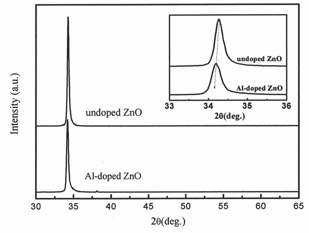
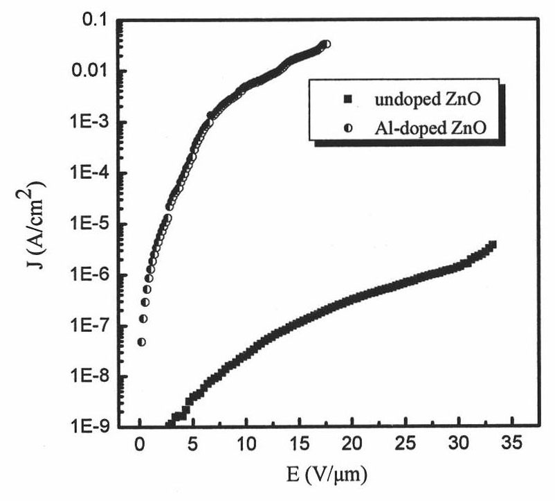
The invention discloses a method for improving the field emission characteristic of film ZnO, which comprises the following steps: firstly, preparing Al doped ZnO ceramic target material; secondly, preparing Al doped ZnO film, cutting the prepared Al doped ZnO film into 0.5cm<2)> to be used as a cathode, using ITO glass as anode, separating the cathode from the anode by using glass thread with 100 micrometers of spacing, and sending KEITHLEY 2410 into a vacuum testing system for the test, wherein the vacuum degree is 5*10 <-7> Pa, the lowest voltage applied between the Al doped ZnO film of the cathode and the ITO glass of the anode is defined as the starting voltage, and the corresponding electric field is the starting field. The method improves the field emission current density of the film ZnO and reduces the field emission starting field strength.
Description
A method for improving field emission characteristics of thin-film ZnO technical field The invention belongs to the technical field of field emission flat panel display, and relates to a preparation technology of a thin-film type field emission material and a method for improving the field emission characteristics of thin-film type ZnO. Background technique "Field emission" has a very wide and important application in vacuum microelectronic devices, such as field emission flat panel displays, high-power electron emission sources, etc., and one of the most critical technologies for these devices is to make cathode electron emitters with excellent performance. Wide bandgap semiconductor ZnO has many excellent properties, especially: good chemical stability, small or even negative electron affinity, high thermal conductivity, oxidation resistance, high temperature resistance, large breakdown field strength And high carrier mobility, large emission current, making it very pop...
Claims
Login to View More Application Information
Patent Timeline
 Patent Type & AuthorityPatents(China)
IPC IPC(8): H01J9/02C23C14/35C23C14/08H01J9/42G01R19/08
Inventor李军
OwnerIRICO