Highly directive antenna based on grooved cross metal strip artificial medium structure

A technology of artificial media and metal strips, which is applied to antenna combinations, antennas, leaky waveguide antennas with different interactions, etc., can solve the problems of processing error antenna performance, difficult precise positioning, inconvenient installation, etc., and achieve good directivity , Avoid antenna performance damage, easy to install and fix

Inactive Publication Date: 2009-09-09
HANGZHOU NORMAL UNIVERSITY
View PDF0 Cites 17 Cited by
  • Summary
  • Abstract
  • Description
  • Claims
  • Application Information

AI Technical Summary

Problems solved by technology

[0005] There is no substrate in the artificial dielectric structure used by Enoch et al. to achieve directional radiation, so the antenna device is fixed with foam with a dielectric constant close to 1, which is inconvenient to install and difficult to locate accurately; the antenna used as a radiation source is a monopole Sub-antenna, this type of antenna cannot be made with planar printed circuit technology, which may easily cause processing errors and damage the performance of the antenna; in order to embed the antenna in the medium, a certain number of dielectric plates need to be placed on both sides of the antenna. In addition, in order not to cause electromagnetic waves To radiate to the other side, it is also necessary to place a flat metal reflector at the bottom of the antenna device, which makes the device larger

Method used


Image

  • Highly directive antenna based on grooved cross metal strip artificial medium structure
  • Highly directive antenna based on grooved cross metal strip artificial medium structure
  • Highly directive antenna based on grooved cross metal strip artificial medium structure

Examples


Embodiment Construction

[0025] The present invention will be further described below in conjunction with the accompanying drawings and embodiments.

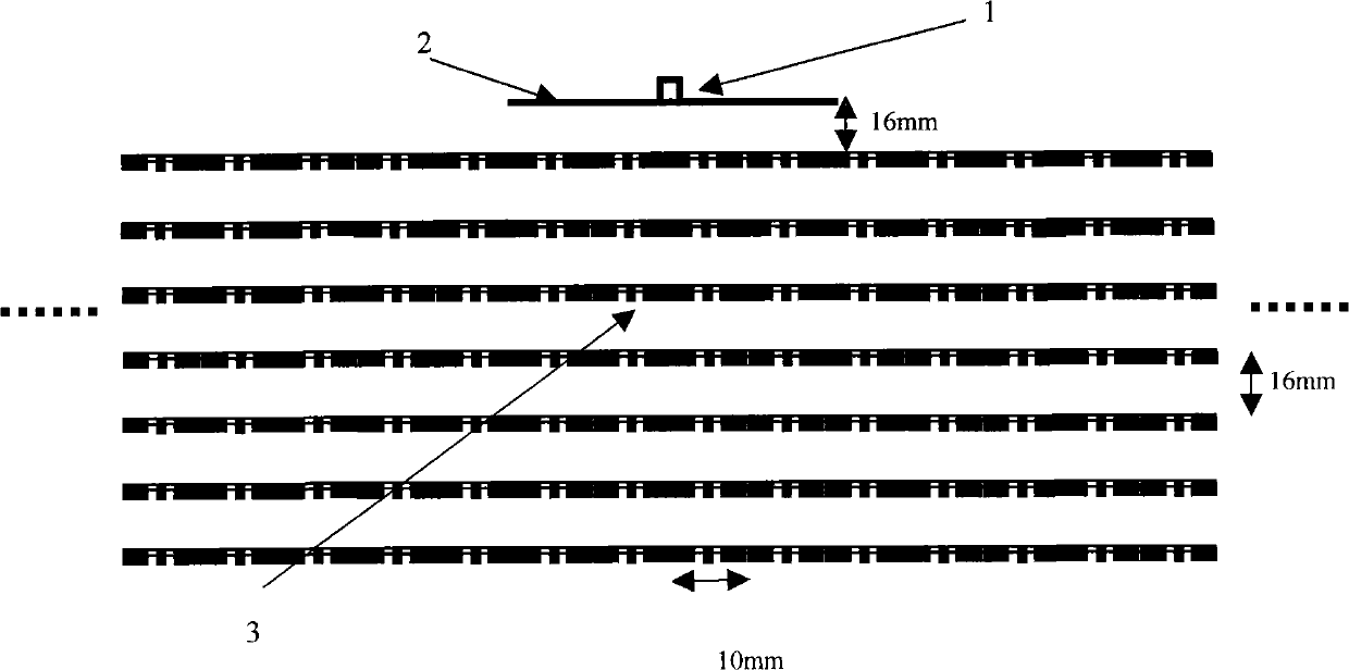
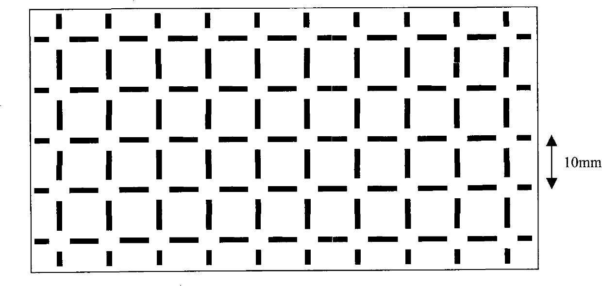
[0026] refer to figure 1 , this figure is a schematic diagram of the overall structure of the high-direction antenna provided by the present invention, including an SMA connector 1, a microstrip antenna array 2 and a radome 3 utilizing a slotted cross metal strip structure; feeding the microstrip antenna array 2 through the SMA connector 1 Energy, electromagnetic waves radiated by the microstrip antenna array 2 are emitted through the radome 3 based on the slotted cross metal strip structure.

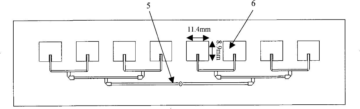
[0027] refer to Figure 4 , the microstrip antenna array is composed of 1×8 8 microstrip patches. The distance from the SMA connector through the microstrip line to each microstrip patch is the same. The impedance of the SMA connector is the standard 50 ohms. In order to match the impedance of the SMA connector with each microstrip patch antenna and achieve th...


PUM


Abstract

The invention discloses a high-gain low-sidelobe highly directive antenna based on an artificial medium structure, comprising a microstrip antenna array and a radome composed of a plurality of grooved cross metal strip artificial medium structures; the grooved cross metal strip structure is printed on a tellite and is used as the radome of the microstrip antenna array; the structure can be equivalent to a homogeneous medium with plasma frequency by rationally designing the cycle and size of the metal structure; the equivalent index of refraction of the frequency of the electromagnetic wave is similar to zero when the frequency is in a certain frequency band. The energy of the electromagnetic wave radiated by the microstrip antenna array is collected in the normal direction of the radome when the electromagnetic wave passes through the radome to achieve the effect of gathering energy, thus improving the overall directivity and gain of the antenna and reducing the sidelobe of the antenna. The antenna not only has the advantages of high gain, good directivity, low sidelobe and the like, but also has the characteristics of good mechanical performance, convenient fixed mounting, simple processing, low cost, small structure size and the like.

Description

technical field [0001] The invention relates to a wireless communication component, specifically a high-gain and low-sidelobe high-direction antenna based on an artificial dielectric structure. Background technique [0002] The artificial periodic metal structure can be used to be equivalent to various homogeneous media, and has characteristics that natural natural materials do not have. It has been proved that the artificial periodic grid structure composed of interwoven metal thin wires can be regarded as a uniform structure with a lower plasma frequency when its characteristic parameters (unit grid size, line width size) are smaller than the wavelength of electromagnetic waves. The dispersion relation of the medium, ie the electromagnetic waves propagating in it, is similar to that of plasma gas. This phenomenon opens up the application of negative materials and artificial media in the microwave and light wave bands, such as perfect lens imaging, various planar microwave...

Claims


Application Information

Patent Timeline
Patent Type & Authority Applications(China)
IPC IPC(8): H01Q21/29H01Q13/08H01Q13/20H01Q19/00
Inventor 朱方明王志宇姜涛冉立新沈林放
Owner HANGZHOU NORMAL UNIVERSITY
Why Eureka
Try Eureka