Space-division system for highly effectively using cold energy of liquefied natural gas

A technology of liquefied natural gas and air separation system, which is applied in liquefaction, cold treatment separation, refrigeration and liquefaction, etc. It can solve problems such as the limitation of conversion efficiency of booster turbo expander, safety threat of main cooling equipment, leakage and pollution of liquid nitrogen products, etc. Achieve the effect of sharp reduction of explosion-proof measurement and control components, avoid irreversible loss, and reliable process

Active Publication Date: 2011-05-25
四川空分设备(集团)有限责任公司
View PDF2 Cites 0 Cited by
  • Summary
  • Abstract
  • Description
  • Claims
  • Application Information

AI Technical Summary

Problems solved by technology

When the circulating nitrogen in this system is pre-cooling and heat-exchanging in the liquefied natural gas heat exchanger, if the high-pressure liquefied natural gas leaks, it will enter the liquid oxygen heat exchanger and the main heat exchanger along with the pipeline, which will affect the main cooling equipment. Threats to safety and pollution of liquid oxygen and liquid nitrogen products
In addition, this system uses the low-pressure nitrogen (~10KPaG) cycle drawn from the top of the upper tower to complete the nitrogen cycle. The ratio needs to be at least 1.1:25, and there are many compression stages, at least three stages are required. In addition, in the whole process, the amount of logistics is large, the energy consumption is high, and the investment is high. In order to improve the safety of the main cooling, liquid oxygen needs to be discharged. It is very complicated to configure the gas-liquid separator, etc.
[0004] Chinese invention patent specification CN101392981 discloses a method and device for obtaining liquid nitrogen by utilizing the cooling capacity of liquefied natural gas. The supercharged turbo expander relies on the expander to transfer cooling capacity, but the conversion efficiency of the supercharged turbo expander is limited, the energy consumption is high due to the conversion of the intermediate link, the device is complicated due to the large number of driving equipment, high investment, and poor reliability. At the same time, it needs to configure gas-liquid separator, etc., which is very complicated

Method used


Image

  • Space-division system for highly effectively using cold energy of liquefied natural gas
  • Space-division system for highly effectively using cold energy of liquefied natural gas
  • Space-division system for highly effectively using cold energy of liquefied natural gas

Examples


Embodiment 1

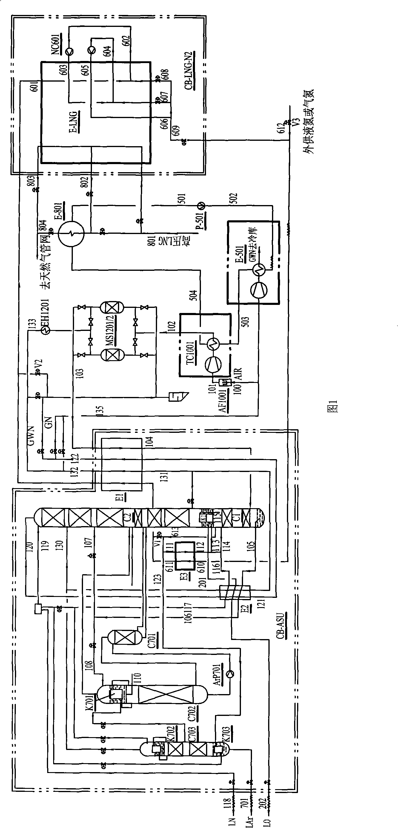
[0039] like figure 1 Shown is a typical device for producing liquid oxygen, liquid nitrogen, and liquid argon according to the present invention.

[0040] 1 air separation system

[0041] 1.1 Compression cooling and purification

[0042] The external air 100 is filtered by the air filter AF1001, and enters the air compressor TC1001 for compression and cooling, and the coolant is cooled by low-temperature circulating coolant.

[0043] The process air 102 enters the adsorber MS1201 / 2 which is used to absorb and remove moisture, carbon dioxide and some hydrocarbons, one absorbs, and the other is regenerated by heating the GWN dirty nitrogen gas 133 from the cold box through the heater EH1201 .

[0044] 1.2 Air distillation

[0045] The clean process air 103 (~460KPaG) exiting the air purification system enters the main heat exchanger E1 in the air separation cold box CB-ASU, is cooled by the gas that flows back out, and the air 104 close to the dew point enters the bottom of ...

Embodiment 2

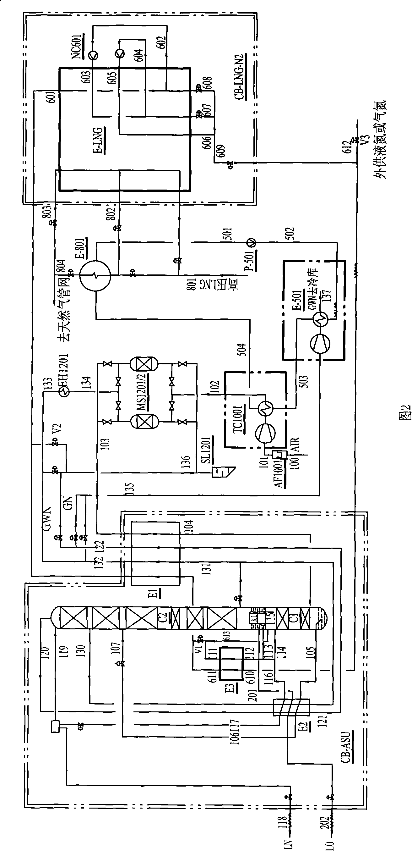
[0068] like figure 2 As shown, compared with Example 1, there is no argon production system, and the others are the same as Example 1. The obtained air separation products are liquid oxygen and liquid nitrogen.

Embodiment 3

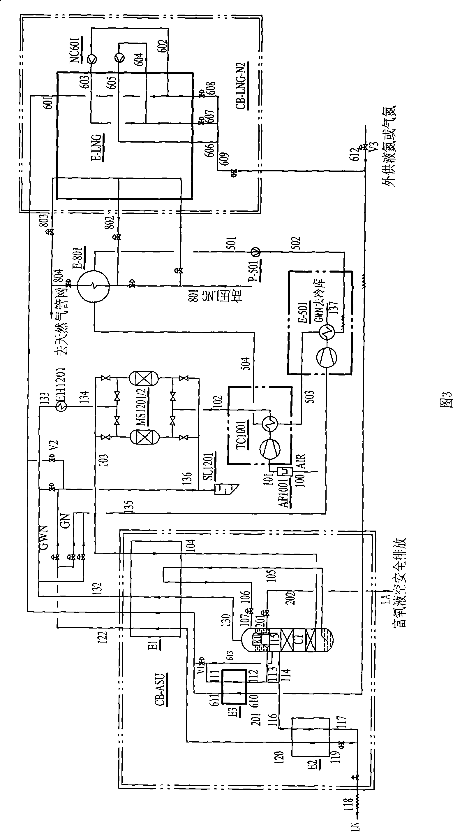
[0070] like image 3 As shown, compared with Example 1, the fractionation tower C1 is a single tower, and after the air enters the fractionation tower, the partial pressure gas nitrogen 111 obtained from the top of the fractionation tower enters the nitrogen-nitrogen heat exchanger E3 to condense into liquid nitrogen 112, and the natural gas nitrogen exchange The liquid nitrogen 610 from the hot and cold box CB-LNG-N2 is vaporized into gas nitrogen 611 (~180KPaG), and enters the main heat exchanger E1 to be reheated as circulating nitrogen 601 (~170KPaG); part of the pure nitrogen 115 enters the top of the fractionation tower The main condensation evaporator K1 is condensed into liquid nitrogen 113 . A part of liquid nitrogen 114 flows down as the reflux liquid of the lower tower, another part of liquid nitrogen 116 is supercooled by cooler E2, and part of it is extracted as product liquid nitrogen 118, and the rest of liquid nitrogen 119 is throttled and passed through cooler...


PUM


Abstract

The invention discloses a space-division system for highly effectively using cold energy of liquefied natural gas (LNG), comprising an LNG-nitrogen heat exchanger and a nitrogen-nitrogen heat exchanger. The pressure nitrogen is used as the closed circulating medium. The liquefied natural gas transfers the cold energy to the circulating nitrogen in the LNG-nitrogen heat exchanger. The circulating nitrogen transfers the cold energy to the pressure nitrogen of a space-division rectification tower in the nitrogen-nitrogen heat exchanger. The space division is not in contact with the circulating medium directly so as to avoid the danger caused by the natural gas entering a space-division device. The circulating nitrogen is cooled by the LNG cold energy so as to reduce the compression power consumption and obtain super-critical pressure nitrogen. In order to make up the disadvantage of the high-grade cold energy of LNG, one path of the high-pressure liquid nitrogen is throttled to the intermediate-pressure pressure, another path of the high-pressure liquid nitrogen is expanded by an expander to recover energy and then partially enters the LNG-nitrogen heat exchanger for deeply superbly cooling the high-pressure liquid nitrogen, and the rest liquid nitrogen enters the space-division system. The number of the channels of the heat exchanger is seldom, the flow organization is simple, safe and reliable, the operation and control are simple, the cost is low, and the application range is wide.

Description

technical field [0001] The invention relates to an air separation system for efficiently utilizing the cold energy of liquefied natural gas. Background technique [0002] As one of the chemical energy sources, natural gas has been gradually promoted as the main energy pillar after coal and oil due to its huge reserves and low pollution, and has broad application prospects. The trade form of natural gas is mainly through pipeline transportation and liquefied natural gas (LNG) transportation. Before LNG enters the pipeline network of natural gas users, it needs to be gasified from the liquefied state to normal temperature. The gasification process will generate huge cooling capacity. By making full use of the gasification cold energy of LNG, the air separation device can greatly reduce power consumption, increase liquid production, and improve the competitiveness of products in the market. The air separation system using LNG cold energy generally saves more than 50% of electr...

Claims


Application Information

Patent Timeline
Patent Type & Authority Patents(China)
IPC IPC(8): F25J3/04F25J5/00
CPCF25J3/0403F25J3/0406F25J3/04157F25J3/04224F25J3/0423F25J3/04272F25J3/04351F25J3/044F25J3/04412F25J3/04678F25J3/04703F25J3/04727F25J3/0489F25J2200/72F25J2210/62F25J2230/04F25J2235/58F25J2240/12F25J2240/30F25J2270/02F25J2270/12F25J2270/904
Inventor 黄震宇易希朗
Owner 四川空分设备(集团)有限责任公司
Why Eureka
Try Eureka