Membrane electrode and current collecting board element of electrochemical cell and electrochemical cell module

A current collection and battery module technology, applied in the field of electrochemical batteries, can solve the problems of high manufacturing cost, high requirements for bipolar plates, complex structure and assembly process, etc., to simplify the structure and assembly process, reduce costs, and increase the effective area The effect of utilization

Inactive Publication Date: 2009-09-16
JIANGSU QINGNENG NEW ENERGY TECHNOLOGIES CO LTD
View PDF2 Cites 8 Cited by
  • Summary
  • Abstract
  • Description
  • Claims
  • Application Information

AI Technical Summary

Problems solved by technology

[0006] In order to overcome the disadvantages of the Chinese case 99808103.5 in the above-mentioned background technology that have higher requirements on the bipolar plate and the effective area utilization rate of the membrane electrode; at the same time, the structure and assembly process in the Chinese application 200610029938.1 in the above-mentioned background technology are relatively complicated, and the manufacturing cost is still Higher disadvantages, the present invention provides a membrane electrode and current collecting plate assembly of an electrochemical cell and an electrochemical cell module

Method used


Image

  • Membrane electrode and current collecting board element of electrochemical cell and electrochemical cell module
  • Membrane electrode and current collecting board element of electrochemical cell and electrochemical cell module
  • Membrane electrode and current collecting board element of electrochemical cell and electrochemical cell module

Examples


Embodiment 1

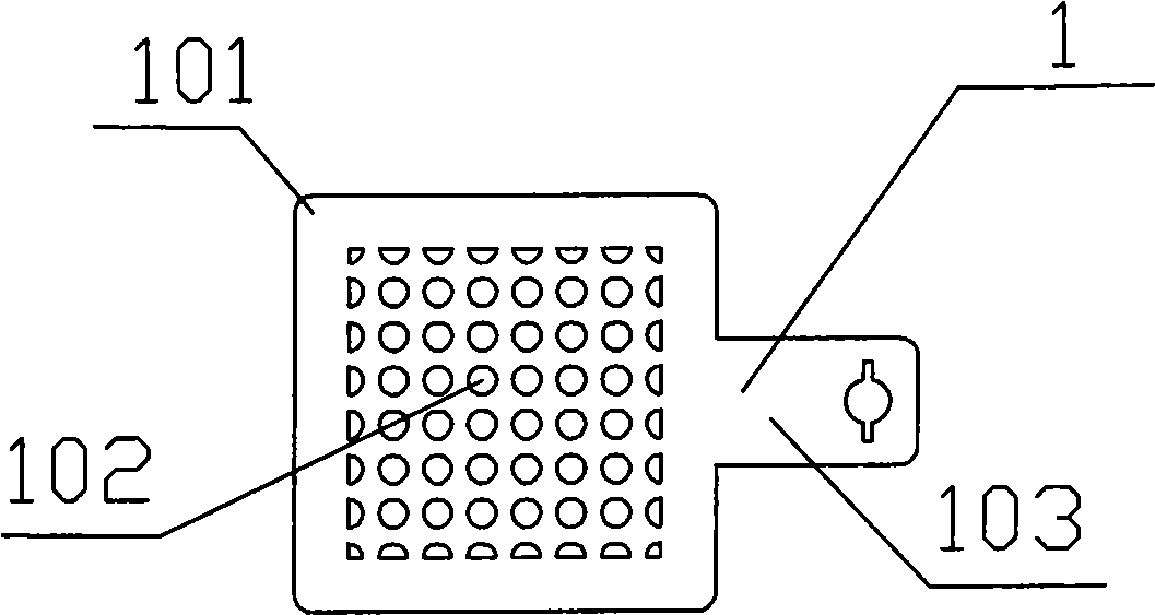
[0031] figure 1 Shown is a metal plate 1 acting as a porous current collector plate on one side, its middle area is covered with tiny through holes, which is the reactive area 101, and its non-porous outer ring is the non-reactive area 102, with a handle-like extension on the right It is the electrical lead-out area 103, and the end of the electrical lead-out area has a through hole for electrical connection.

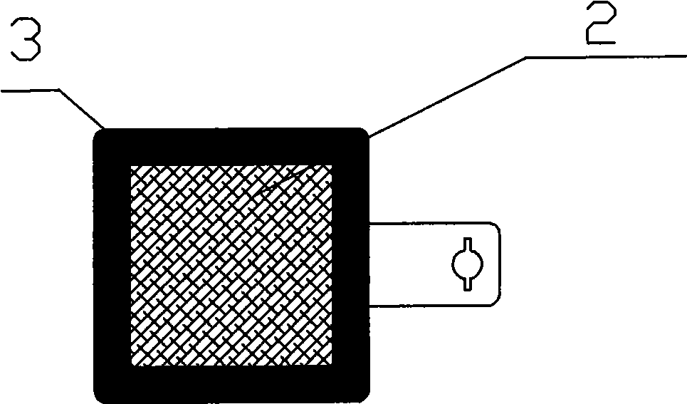
[0032] figure 2 Shown is an intermediate product with carbon paper 2 as a gas diffusion layer on one side and glue 3 as a sealing material; the area of ​​carbon paper 2 basically corresponds to the reaction area 101 of metal plate 1; the position of glue 3 is the same as that of the metal plate The non-reactive region 102 of 1 basically corresponds.

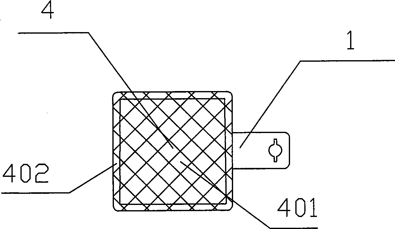
[0033] image 3 Shown is the assembly with a membrane 4 added, the middle part of the membrane 4 being the reaction zone 401 and the outer circle being the non-reaction zone 402 .

[0034] The glue 3 fills the space ...

Embodiment 2

[0038] Figure 5 It is an extension of the component shown in Example 1. The carbon paper 5 serving as the gas diffusion layer on the other side, the metal plate 6 serving as the porous current collecting plate on the other side, and the glue 7 serving as the sealing material are added.

[0039] The positional relationship of carbon paper 5, metal plate 6, and glue 7, the distribution of reaction area, non-reaction area and electric lead-out area are similar to the situation of metal plate 1, film 4 and carbon paper 2 in Example 1, and the attached figure is clear enough , no longer numbered for each region.

Embodiment 3

[0041] Figure 6 It is an extension of the component shown in Example 1. A metal plate 6 acting as a porous current collecting plate on the other side and a glue 7 acting as a sealing material are added. Since this assembly is used to assemble the electrolytic cell module, the electrolytic cell has a high polarization overvoltage during operation, in order to avoid galvanic corrosion, there is no carbon paper 5, so the glue 7 is very thin and can hardly be seen in the figure. Other positional relationships are similar to Example 2.


PUM

PropertyMeasurementUnit
widthaaaaaaaaaa

Abstract

The invention discloses a membrane electrode and current collecting board element of an electrochemical cell, which comprises a layer of membrane, a lateral gas diffusion layer and a lateral porous current collecting board that are superposed in sequence; the lateral gas diffusion layer is arranged on the lateral porous current collecting board and the middle of the membrane; and the side surface of the periphery of the lateral gas diffusion layer is filled with sealing materials and solidified. The invention also discloses an electrochemical cell module comprising at least one electrochemical single cell; and the electrochemical single cell comprises an end plate with a gas flow passage at one side, an element and an end plate with a gas flow passage at the other side that are superposed in sequence. Compared with the prior art, the technical proposal simplifies the structure and the assembly technology, thus reducing the cost of production in batches, improving the utilization rate of the effective area of the membrane electrode simultaneously and being applicable to production of fuel cells, electrolytic cells, regenerative fuel cells and electrochemistry oxygen generators.

Description

technical field [0001] The invention relates to the field of electrochemical cells, in particular to an electrochemical cell membrane electrode, a current collecting plate assembly and an electrochemical cell module. Background technique [0002] The Chinese case 99808103.5 of the international patent discloses an airtight assembly composed of a bipolar plate and a membrane electrode unit of a polymer electrolyte membrane fuel. The bipolar plates and membrane electrode units are bonded with curable polymers. The airtight assembly is obtained by coating adhesive beads around the outside of the gas chamber and around the inner gas conduit. These assemblies can be stacked and bonded together according to the invention to form a polymer electrolyte fuel cell stack. [0003] Compared with the previous technology, the above-mentioned technical solution has certain progress. However, in addition to the role of drawing voltage and current, the bipolar plate also plays the role of...

Claims


Application Information

Patent Timeline
Patent Type & Authority Applications(China)
IPC IPC(8): H01M8/02H01M4/86H01M8/10H01M8/24C25B9/10C25B9/18C25B9/23
CPCH01M2008/1095Y02E60/50H01M8/0269H01M8/0284Y02P70/50
Inventor 顾志军
Owner JIANGSU QINGNENG NEW ENERGY TECHNOLOGIES CO LTD
Why Eureka
Try Eureka