High-effective integral spray cooling system

A spray cooling, integrated technology, applied in cooling/ventilation/heating transformation, electric solid devices, semiconductor devices, etc., can solve the problems of large heat exchange area, heat transfer temperature difference, increased flow resistance, etc., to reduce heat exchange Area, reduce flow resistance, improve heat transfer effect

Inactive Publication Date: 2009-09-16
UNIV OF SCI & TECH OF CHINA +1
View PDF4 Cites 43 Cited by
  • Summary
  • Abstract
  • Description
  • Claims
  • Application Information

AI Technical Summary

Problems solved by technology

In this design, the latent heat of evaporation of the liquid is simply used, coupled with the thermal resistance of the heat-absorbing plate, the temperature of the heat source is often higher than the saturation temperature of the liquid, which makes the operating temperature of the electronic device exceed the allowable range; the flow of the working fluid depends on the

Method used


Image

  • High-effective integral spray cooling system
  • High-effective integral spray cooling system
  • High-effective integral spray cooling system

Examples


Embodiment 1

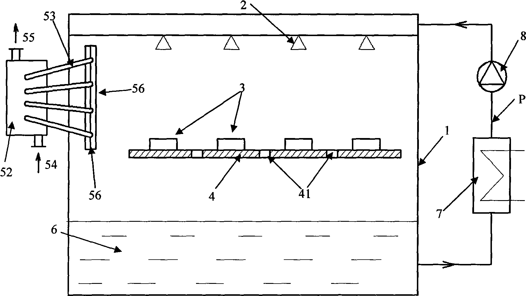
[0023] see figure 1 , figure 2 The high-efficiency integrated spray cooling system includes a spray chamber 1, a heat pipe heat exchanger, a liquid cooler 7, a circulation pump 8 and a system working fluid circulation pipeline P, and a spray mechanism 2 is installed on the top of the spray chamber 1, and an orifice plate is installed in the middle 4. Guide holes 41 are evenly distributed on the orifice plate, electronic components 3 are evenly distributed on the orifice plate 4, and a liquid reservoir 6 is arranged at the bottom, and the liquid reservoir 6 is connected with the liquid cooler 7, the circulation pump 8, And the spray mechanism 2 is connected. A heat pipe heat exchanger is used as a steam condenser.

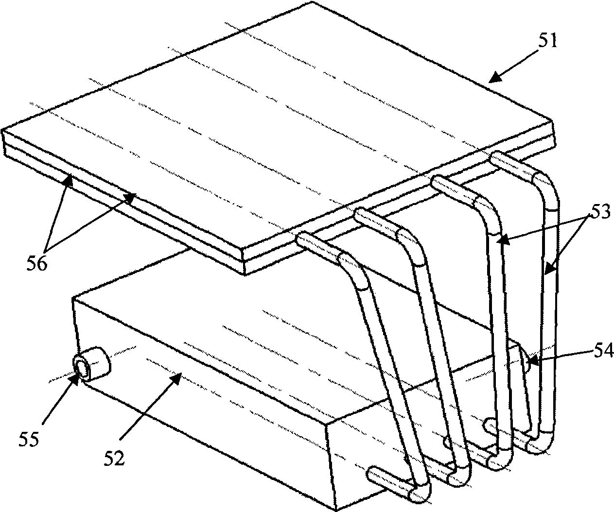
[0024] One end of the heat pipe 53 of the heat pipe heat exchanger is the condensation end 52, and the other end of the heat pipe 53 is the evaporation end 51, which is a steam condenser; the evaporation end is located inside the spray chamber to provide condensa...

Embodiment 2

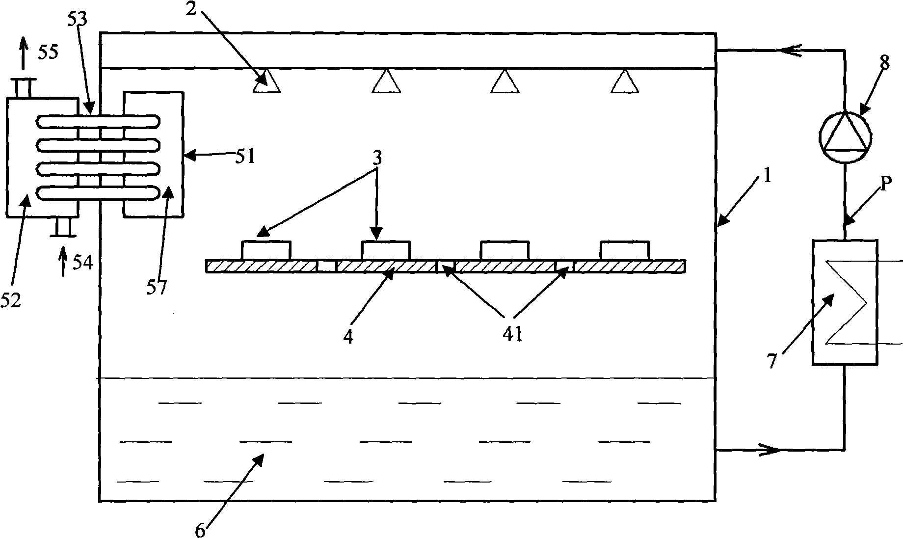
[0031] see image 3 , Figure 4 , the system uses a heat pipe heat exchanger as a steam condenser. The evaporating end 51 of the heat pipe heat exchanger is located inside the spray chamber 1 to provide condensation for the steam; the condensing end 52 of the heat pipe condenser is located outside the spray chamber to remove the condensation and heat dissipation of the steam out of the spray chamber; the heat pipe heat exchanger includes four heat pipes Fins 57 are evenly distributed on the evaporating end 51, and the condensing end 52 is located in the water-cooled shell-and-tube heat exchanger outside the spray chamber. There is a cooling water inlet 54 at the bottom of one side of the water-cooled shell-and-tube heat exchanger, and there is The cooling water outlet 55; the middle part of the heat pipe 53 passes through and is fixed on the side wall of the spray chamber 1, and the joint between the heat pipe and the side wall of the spray chamber can be sealed by means of a...

Embodiment 3

[0035] see Figure 5 , the liquid reservoir 6 and the liquid cooler 7 are combined to form a liquid storage cooler 67, which is arranged at the bottom of the spray chamber 1.

[0036] When the present embodiment works, the working medium cooled by the liquid cooler 7 enters the spray mechanism 2 of the spray chamber 1 after the circulation pump 8 increases the pressure and atomizes, and sprays on the surface of the electronic component 3 to cool and dissipate the surface of the electronic component 3 , the non-vaporized working fluid flows through the surface of the electronic component 3, and flows into the liquid storage cooler 67 through the orifice plate 4; part of the working fluid vaporizes due to absorbing heat from the electronic component 3 and forms steam, which is recondensed into liquid on the surface of the condenser Flow into the liquid storage cooler 67; after the working medium in the storage liquid cooler 67 is cooled to the required temperature by the cooler ...


PUM

PropertyMeasurementUnit
Thermal conductivityaaaaaaaaaa
Thicknessaaaaaaaaaa
Thermal conductivityaaaaaaaaaa

Abstract

The invention relates to a high-effective integral spray cooling system, which solves heat dissipation problem in field such as high power electron or laser system. The spray cooling system includes a spray cavity, a heat exchanger, a cooler, a circulating pump and a system working medium circulation pipeline, wherein the heat exchanger is a heat pipe heat exchanger; one end of the heat pipe of the heat pipe heat exchanger is a condensation end, and the other end is an evaporation end; the evaporation end is arranged in the spray cavity and is a steam condenser, and the condensation end is arranged in a water cooling shell-and-tube heat exchanger outside the spray cavity. The invention separates steam cooling and liquid cooling, which is beneficial to respectively increase heat transfer effect in condensation and cooling process; employs the heat pipe condenser to further increase heat transfer performance in condensation process and reduce heat exchange area of the condenser; and arranges the condenser in the spray cavity for making spray cooling structure more compact and reducing flow resistance of working medium steam, thereby reducing operating pressure of the spray cavity and being beneficial to increase general heat dispersion performance of spray cooling.

Description

technical field [0001] The invention relates to the cooling of a heat source with high heat flux density, in particular to a high-efficiency integrated spray cooling system. Background technique [0002] Traditional heat dissipation methods such as natural convection and forced convection are increasingly unable to meet the increasing heat dissipation requirements of electronic components. The normal operating temperature range of electronic devices is generally -5°C to 65°C, beyond this range, the performance of electronic components will drop sharply. Due to its strong heat dissipation ability, the spray cooling heat dissipation technology has broad application prospects for solving heat dissipation problems in aerospace, high-power electronic systems, high-power laser systems and other fields. The heat dissipation technology in the above fields must have the characteristics of high heat dissipation capacity, less auxiliary facilities, low energy consumption, small size, ...

Claims


Application Information

Patent Timeline
IPC IPC(8): H05K7/20H01L23/427F28D15/02
Inventor 程文龙范含林刘期聂赵锐
Owner UNIV OF SCI & TECH OF CHINA
Why Eureka
Try Eureka