Clean incineration system of refuse and organic wastes and device thereof

A technology for organic waste and purification equipment, applied in lighting and heating equipment, incinerators, combustion methods, etc., can solve the problems of low cost, complex flue gas purification system, and high pollutant content

Inactive Publication Date: 2009-10-21
周开根
View PDF0 Cites 18 Cited by
  • Summary
  • Abstract
  • Description
  • Claims
  • Application Information

AI Technical Summary

Problems solved by technology

At present, China's domestic waste treatment mainly includes sanitary landfill technology, composting (biochemical) technology and incineration technology. Most areas use sanitary landfill method to deal with domestic waste, which not only takes up a lot of land, wastes resources, but also easily pollutes land and groundwater; composting only utilizes about 40% of organic matter, and it is necessary to build supporting incineration process equipment and sanitary landfills. Heavy metals in composting products may pollute the soil and enter the food chain crops, and there are also secondary Hidden dangers of secondary pollution; the incineration method is used to deal with urban domestic waste, and the waste heat is used for power generation or heat supply, which can reduce the amount a

Method used


Image

  • Clean incineration system of refuse and organic wastes and device thereof
  • Clean incineration system of refuse and organic wastes and device thereof
  • Clean incineration system of refuse and organic wastes and device thereof

Examples


Embodiment Construction

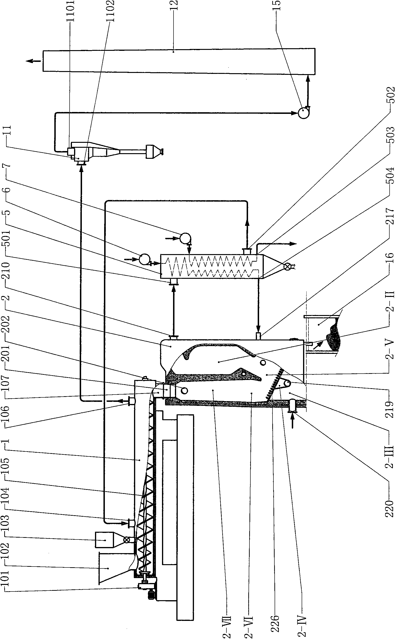
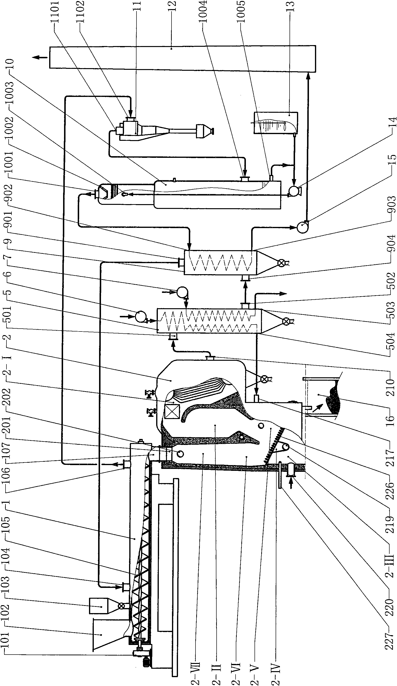
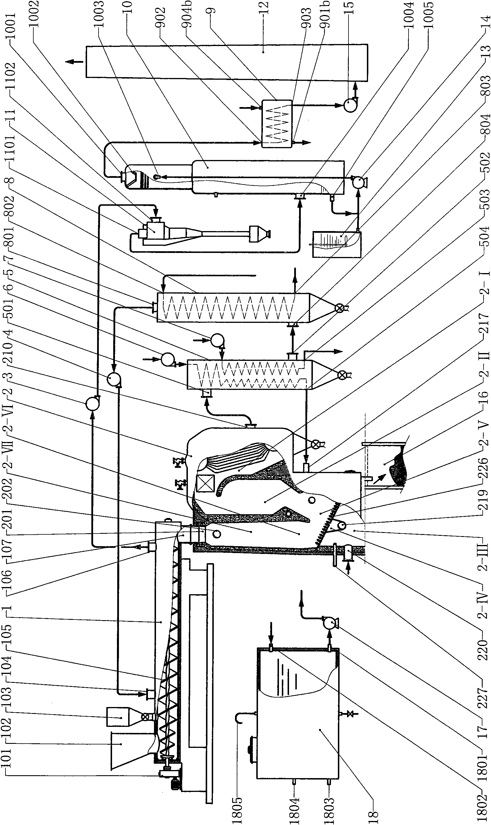
[0031] figure 1 The illustrated embodiment is a system for treating high-moisture domestic waste by clean incineration suitable for small-scale waste incineration plants in villages and towns. The system mainly consists of air dryer (1), incinerator (2), air preheater (5), It consists of cyclone dust collector (11), induced draft fan (15), chimney (12) and connecting pipes, wherein: the air dryer (1) is a horizontal cylindrical device, and an insulation layer is arranged outside the cylinder, and the front of the air dryer (1) Garbage hoppers (102), additive hoppers (103) and air outlets (104) are arranged in sequence at the front, air exhaust outlets (106) are arranged at the rear, and the discharge port (107) of the air dryer is at the tail. The screw conveyor (105) is used to convey the garbage material in the air dryer from front to back, and the screw conveyor (105) is driven by the gearbox (101) outside the device; the incinerator (2) is a gas phase circulation incinerat...


PUM


Abstract

A clean incineration system of refuse and organic wastes and a device thereof relate to refuse incineration equipment. The incineration system mainly consists of an dry fan, a gas phase circulating incinerator, an air preheater, a dedusting/purification device, an induced draft fan and a chimney, a discharge outlet of the dry fan is connected to a feed inlet of the incinerator, a fume outlet of the incinerator is connected to the air preheater, the air preheater is connected to an air supply outlet of the dry fan, a suction opening of the dry fan is connected to a fume inlet of the dedusting/purification device, and a fume outlet of the dedusting/purification device is connected to the chimney by the induced draft fan. A dry distillation zone and a gasification zone form a gasification environment, and a first combustion zone and a second combustion zone form a combustion environment in the gas phase circulating incinerator, and a circulating air conduit and a circulating fan form a gas phase circulation loop outside the incinerator. Refuse fuel is gasified in the incinerator for combustion, and gaseous material generated in the gasification environment is allowed to have circulating gasification and combustion. The system and the device have the advantages of high burnout ratio, few pollutants generated from combustion and clean incineration of refuse.

Description

Technical field [0001] The invention relates to garbage and organic waste treatment equipment, in particular to garbage incineration equipment. Background technique [0002] At present, the energy shortage and the environmental protection situation are grim. With the development of my country's national economy and the continuous expansion of urban scale, garbage is increasing rapidly, and its content of harmful components is getting higher and higher. If it is not handled properly, it will pollute the environment and threaten people's health. This will not only restrict The progress of the society also affects the sustainable development of the national economy. At present, China's domestic waste treatment mainly includes sanitary landfill technology, composting (biochemical) technology and incineration technology. Most areas use sanitary landfill method to deal with domestic waste, which not only takes up a lot of land, wastes resources, but also easily pollutes land and ...

Claims


Application Information

Patent Timeline
IPC IPC(8): F23G5/04F23G5/46F23G5/44F23J15/00F23L15/00F23G5/027
CPCY02E20/34
Inventor 周开根
Owner 周开根
Why Eureka
Try Eureka