
Novel internal circulation moving bed biological film reactor

A moving bed biofilm and reactor technology, which is applied in the field of new internal circulation moving bed biofilm reactor, can solve the problems of slow proliferation of nitrifying bacteria, increased infrastructure investment and operating costs, and low efficiency of organic matter treatment.

Inactive Publication Date: 2009-10-28
CHINESE RES ACAD OF ENVIRONMENTAL SCI
View PDF0 Cites 19 Cited by
  • Summary
  • Abstract
  • Description
  • Claims
  • Application Information

AI Technical Summary

Problems solved by technology

Due to the different bacterial flora involved and the different operating parameters of the process, the two processes of nitrification and denitrification need to be carried out in two isolated reactors, or in the same reactor that alternately anoxic and aerobic environments in time or space Therefore, it is necessary to add an external circuit to return the sludge and nitrifying liquid or to increase the time and space sequence control system, which increases the power consumption and operating costs, and brings inconvenience to the actual operation.
In addition, the growth rate of nitrifying bacteria is slow and it is difficult to maintain a high biological concentration, resulting in a long total hydraulic retention time of the traditional activated sludge system, low organic load, and low organic matter treatment efficiency, which increases infrastructure investment and operating costs

Method used


Image

  • Novel internal circulation moving bed biological film reactor

Examples


Embodiment 1

[0020] The simulated wastewater was treated using the above-mentioned embodiment. Reactor size: D 20cm×L 40cm×H 40cm, effective volume 30L, filler filling ratio 40%, flow rate of submerged pump in anoxic section 2.0L / min, aeration rate in aerobic section 1.0L / min, adjust combined perforation The plate porosity is 15%, and the average influent COD 295.5mg / L, NH 4 + -N 37.08mg / L, TN 39.90mg / L, adjust the reactor water flow rate 10L / h, hydraulic retention time 3h, the reactor runs stably for 1 month, the average effluent COD 18.19mg / L, NH 4 + -N 5.07mg / L, TN 6.08mg / L, the average removal rate of pollutants is 93.8% for COD, NH 4 + -N 86.3%, TN 84.8%.

Embodiment 2

[0022] The simulated wastewater was treated using the above-mentioned embodiment. Reactor size: D 20cm×L 40cm×H 40cm, effective volume 30L, filler filling ratio 60%, flow rate of submerged pump in anoxic section 3.0L / min, aeration rate in aerobic section 2.0L / min, adjust combined perforated plate The porosity is 2%, and the average influent COD is 297.0mg / L, NH 4 + -N 36.70mg / L, TN 39.20mg / L, influent flow rate 3.75L / h, hydraulic retention time 8h, reactor running stably for 1 month, effluent COD 14.19mg / L, NH 4 + -N 3.44mg / L, TN 4.33mg / L, the average pollutant removal rate is 95.2% for COD, NH 4 + -N 90.6%, TN 89.0%.


PUM


Abstract

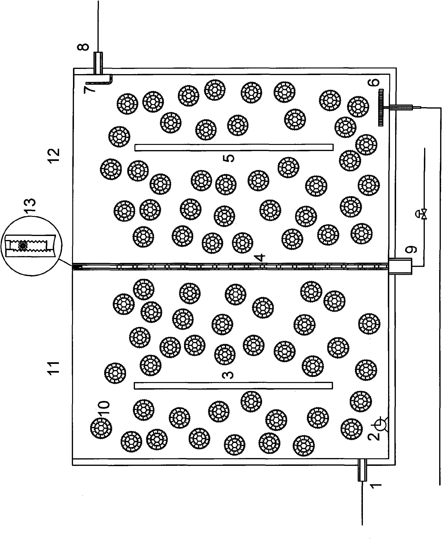
The invention relates to an internal circulation moving bed biological film reactor, which is separated into an anaerobic zone and an aerobic zone by three layers of combined perforated boards. The top of the combined perforated boards is provided with a porosity regulating bolt. A suspension filler is filled in the reactor. The anaerobic zone is installed with an undercurrent pump on the bottom in front and a guide plate in middle. A clockwise hydraulic circular flow is formed in the anaerobic zone under the pushing of the undercurrent pump. The aerobic zone is equipped with an aeration head on the bottom at back and a guide plate in middle. An anticlockwise hydraulic circular flow is formed in the aerobic zone under the action of aeration. The mixing liquid is refluxing from the aerobic zone to the anaerobic zone, driven by the opposite circular flows of two zones, thus efficiently removing the organic matter and realizing nitrogen removal by nitrifying and denitrifying. A waterinlet is arranged on the bottom in the front of the reactor. An overflow weir and a water outlet are arranged on the top of the back end. A sludge outlet is located on the bottom. The reactor has compact conformation and high treatment efficiency.

Description

technical field [0001] The invention belongs to biofilm technology wastewater treatment equipment, in particular to a novel internal circulation moving bed biofilm reactor. Background technique [0002] Excessive ammonia nitrogen content in the water body will cause eutrophication of the water quality, resulting in the overgrowth of some algae in the water body, and the growth of other organisms will be affected, thereby destroying the aquatic ecosystem, leading to deterioration of water quality and affecting its use function. [0003] Biological denitrification technology is currently the most widely used wastewater denitrification technology. Although the nitrification process can convert ammonia nitrogen into nitrate and eliminate ammonia nitrogen pollution, it cannot completely eliminate nitrogen pollution. Although the denitrification process can eradicate nitrogen pollution, it cannot directly remove ammonia nitrogen. Therefore, the traditional biological denitrifica...

Claims


Application Information

Patent Timeline
Patent Type & Authority Applications(China)
IPC IPC(8): C02F3/30
Inventor 宋永会邱光磊彭剑峰袁鹏崔晓宇
Owner CHINESE RES ACAD OF ENVIRONMENTAL SCI
Learn More