
Magnetic head gimbal assembly, manufacturing method thereof and disk drive unit

A magnetic head and foldable technology, which is applied to align the tracks on the magnetic disk, magnetic recording, and maintain the alignment of the head frame, etc., can solve the problems of difficult welding, long process time, difficult installation and operation, etc. The effect of shortened process time and easy operation control

Inactive Publication Date: 2009-11-18
SAE MAGNETICS (HK) LTD
View PDF0 Cites 4 Cited by
  • Summary
  • Abstract
  • Description
  • Claims
  • Application Information

AI Technical Summary

Problems solved by technology

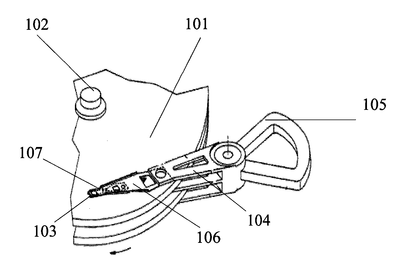
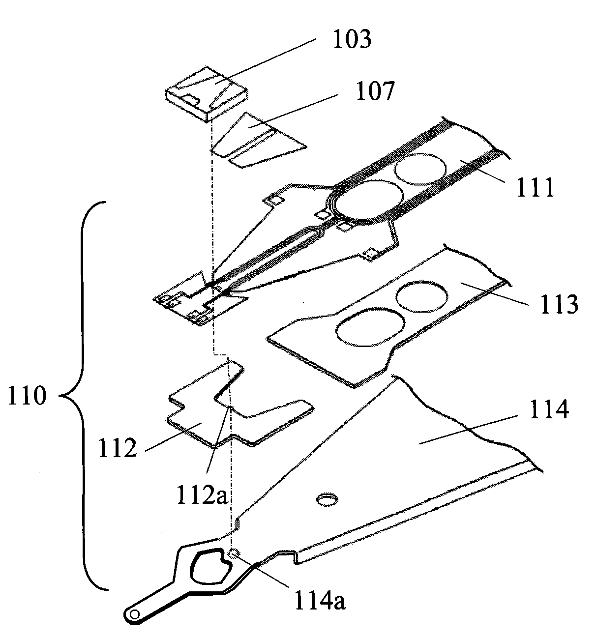
[0007] However, the piezoelectric element 107 and the cantilever 110 in the prior art are manufactured separately in different processes and factories, and the piezoelectric element 107 is mechanically and electrically connected to the cantilever 110 through an assembly process. It is very complex, and at the same time, the head gap combination produced has low yield, poor performance, and long process time
First, since the piezoelectric element 107 is a thin-film piezoelectric element, its thickness is only about 1-10um and it is very fragile, so the piezoelectric element 107 is easily deformed and damaged, and its installation operation is relatively difficult.
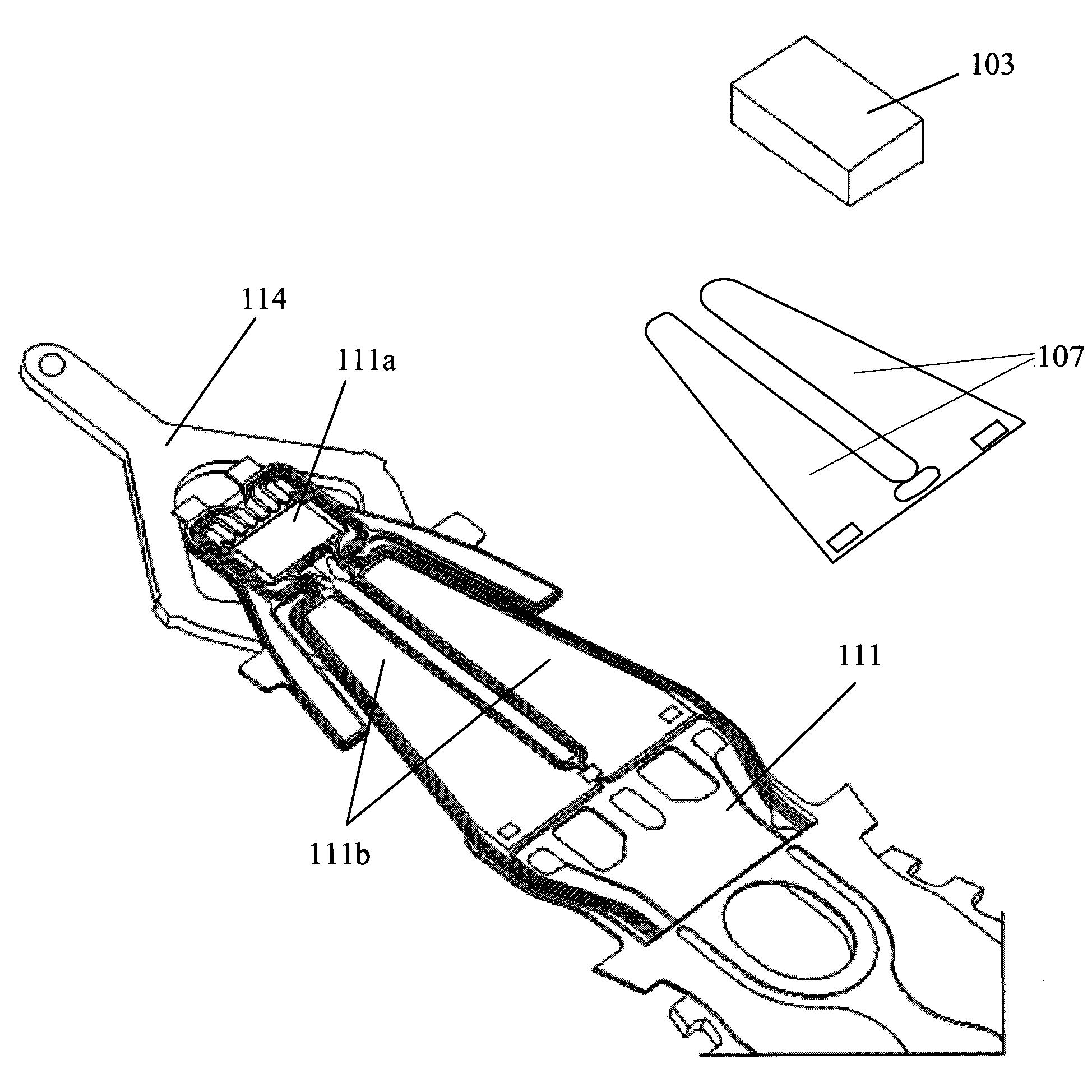
In addition, since the mechanical mounting of the piezoelectric element 107 to the tongue region 111b of the flexible member 111 is accomplished by adhesive bonding, control of the adhesive (such as adhesive viscosity, adhesive strength, adhesive thickness) etc.) are more difficult, and at the same time, since the amount of adhesive will affect the mechanical properties, dynamic properties and static properties of the head gimbal assembly, such as displacement performance and resonance performance, its thickness and volume must be appropriate
This increases the difficulty of controlling the amount of adhesive used in the piezoelectric element 107 installation process
In addition, since the connection position between the piezoelectric element 107 and the suspension member 110 is in the tongue area 111b of the flexible member 111, and the electrical connection is completed by welding, the welding is difficult, so the production rate of the head gimbal assembly is low and time-consuming. large and unreliable

Method used


Image

  • Magnetic head gimbal assembly, manufacturing method thereof and disk drive unit
  • Magnetic head gimbal assembly, manufacturing method thereof and disk drive unit
  • Magnetic head gimbal assembly, manufacturing method thereof and disk drive unit

Examples


Embodiment Construction

[0064] Embodiments of the present invention will now be described with reference to the drawings, in which like reference numerals represent like elements. As mentioned above, the present invention aims to provide a HGA and its manufacturing method, Figure 2a-9 A first embodiment of the HGA 300 of the present invention is described. see Figure 2a-2b , the HGA 300 mainly includes a magnetic head 310 , a suspension 330 carrying the magnetic head, and a micro-actuator 320 formed on the suspension 330 with a piezoelectric layer. The suspension member 330 includes a load bar 430 , a base plate 530 , a pivot member 630 and a flexible member 730 connected together. In this embodiment, the flexible member 730 , the load bar 430 and the base plate 530 are integrated by laser welding. The flexure 730 provides a number of cantilevered contacts 731 which are connected to a control system. In order to transfer the load force from the load bar 430 to the magnetic head 310 smoothly and...


PUM


Abstract

The invention relates to a magnetic head gimbal assembly which comprises a cantilever part, a transition layer and a piezoelectric element, wherein the transition layer is formed on a piezoelectric element bearing area of a flexible element of the cantilever part; the piezoelectric element is deposited on the transition layer; and the piezoelectric element is electrically connected with the cantilever part to form a micro actuator. In the invention, the manufacture, the mechanical assembly and the electric connection of the piezoelectric element and the cantilever part are simultaneously carried out, thus the operation procedure is simple, the process time is short, the productivity of the magnetic head gimbal assembly is high, and the mechanical property, the dynamic property and the static property are good. In addition, the transition layer is formed on the flexible element first, and then the piezoelectric element is formed, wherein the transition layer is made of metal material, metal oxide, non-metal material or inorganic salt. The use of the transition layer ensures easy operation control and is helpful to improve the property of the head gimbal assembly. Moreover, the electric connection of the piezoelectric element and the cantilever part can be realized by a spraying process, a printing process or an electroplating process, thus the difficulty in operation is small and the connection reliability is good. The invention discloses a method for manufacturing the magnetic head gimbal assembly and a disk drive unit.

Description

technical field [0001] The present invention relates to an information recording disk drive unit, in particular to a head gimbal assembly (HGA, head gimbal assembly), a manufacturing method thereof, and a disk drive unit. Background technique [0002] A disk drive unit is an information storage device that uses a magnetic medium to store data, and has a movable magnetic read / write head positioned on the magnetic medium to selectively read data from or write data to the magnetic medium. [0003] Consumers have always expected increasing storage capacity from such disk drive systems, while at the same time expecting faster and more accurate read and write speeds. Therefore, disk manufacturers have been devoting themselves to developing disk systems with higher storage capacity, such as increasing the density of magnetic tracks by reducing the track width or track spacing on the disk, thereby indirectly increasing the storage capacity of the disk. However, as the track density...

Claims


Application Information

Patent Timeline
Patent Type & Authority Applications(China)
IPC IPC(8): G11B5/48G11B5/596
CPCG11B5/4853G11B5/5552G11B5/483
Inventor 姚明高
Owner SAE MAGNETICS (HK) LTD
Learn More