
Novel energy-saving power regulator

A power conditioner and power conditioning technology, applied in the direction of AC network voltage adjustment, reactive power adjustment/elimination/compensation, reactive power compensation, etc. Internal power factor, etc.

Inactive Publication Date: 2009-11-25
北京博旺天成科技发展有限公司
View PDF0 Cites 16 Cited by
  • Summary
  • Abstract
  • Description
  • Claims
  • Application Information

AI Technical Summary

Problems solved by technology

The occurrence of three-phase voltage imbalance will lead to the occurrence of several times current imbalance
Induce the reverse torque in the motor to increase, so that the temperature of the motor will rise, the efficiency will decrease, the energy consumption will increase, vibration will occur, and the output loss will be affected.
The imbalance between the phases will shorten the service life of the electrical equipment, accelerate the replacement frequency of equipment parts, and increase the cost of equipment maintenance
The allowable current margin of the circuit breaker is reduced, and overload and short circuit are prone to occur when the load changes or alternates
Excessive unbalanced current flows into the neutral wire, causing the neutral wire to thicken
[0005]2. Influence on line loss
[0006] In order to solve the problem of unbalanced three-phase voltage, a three-phase balanced system based on zig-zag transformers is usually used. The disadvantage of this method is: large capacity The transformer is bulky
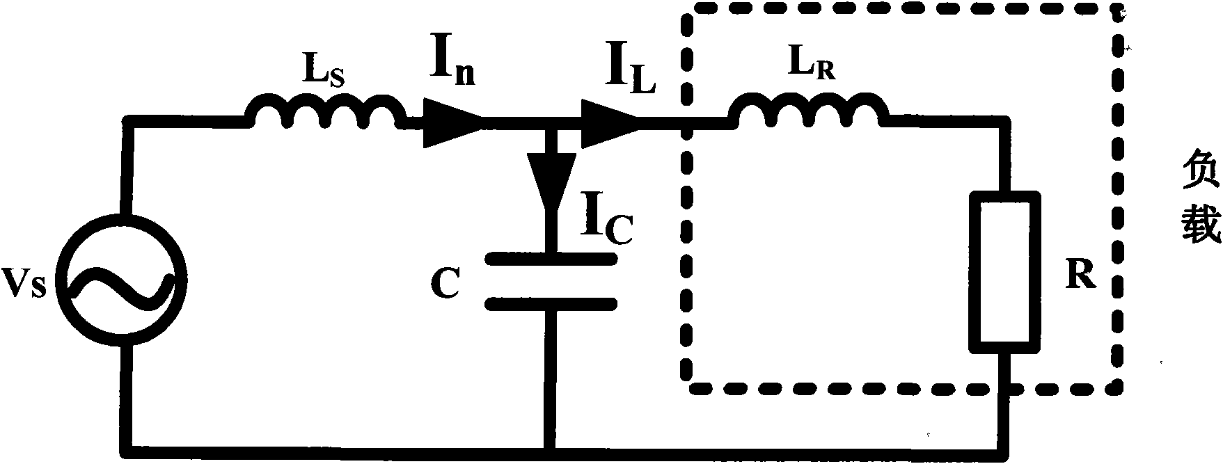
[0009] Take a transformer in an inductive load as an example, such as figure 1 As shown, when performing capacitor reactive power compensation, in the prior art, a voltage stabilizer (not shown in the figure) is first connected to the output end of the transformer. Usually, a parallel capacitor compensation method is used, and a capacitor is connected in parallel at the output end of the voltage stabilizer. figure 1 The dotted line box represents the equivalent load of the inductive load transformer. By adding a capacitor C with a fixed value in parallel to the load voltage input terminal, some power factors can be improved, but the disadvantage of this method is that: because the capacitor C is connected in parallel at the load input terminal, it It can purify the power grid and ensure that the load does not pollute the power grid, but it cannot compensate the inductance of the load circuit, and it cannot improve the power factor inside the load circuit.
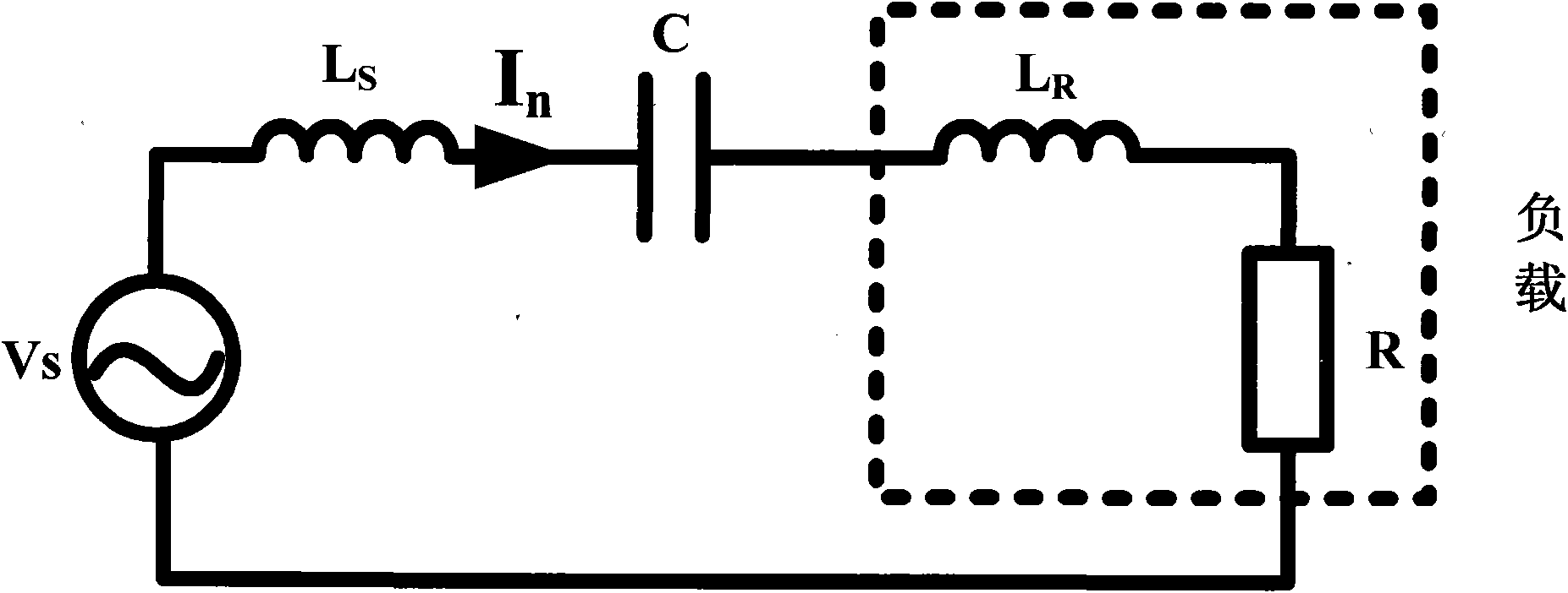
However, the disadvantage of series reactive power compensation is that when the capacitor C is adjusted for reactive power compensation, since the capacitor is connected in series in the load circuit, this will cause the voltage amplitude at both ends of the load to change
Therefore, although the method of series capacitor has the advantage of compensating the reactive power in the load circuit, it has not been adopted yet.

Method used


Image

  • Novel energy-saving power regulator
  • Novel energy-saving power regulator
  • Novel energy-saving power regulator

Examples


Embodiment Construction

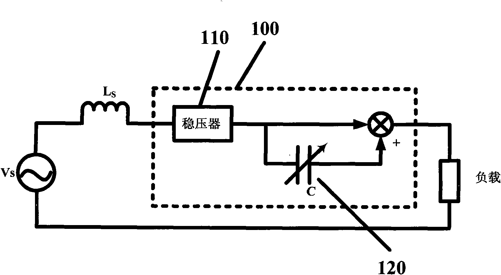
[0051] The technical principle of the present invention is mainly: on the load side of the three-phase electrical system, the input voltage is compensated by using a series power frequency transformer, and a voltage stabilizer and a variable capacitance unit are connected in series at the same time, so that the output can be adjusted. The amplitude of the three-phase voltage at the terminal can also adjust the phase angle, which not only stabilizes the output voltage, but also balances the three-phase voltage.

[0052] Based on the above principles, the present invention proposes a power regulator circuit design model such as image 3 shown, it should be noted that, image 3 What is shown is only an equivalent schematic diagram of the single-phase load side in the three-phase electrical system of the present invention, and the present invention is aimed at a three-phase circuit in actual use.

[0053] image 3 Among them, Vs represents the power supply voltage of the grid, a...


PUM


Abstract

The invention provides a power regulation circuit, a regulator and a voltage regulation method for three-phase AC circuits, wherein an AC power regulator is connected with load sides of circuits of each phase in a three-phase AC power system; on the basis of connecting a voltage stabilizer in series with a power frequency transformer to compensate input voltage, a variable capacitance unit is also connected in series; and by adjusting the transformation ratio d' of the transformer of each phase and the transformation ratio d of an AC chopper, the output voltage of three-phase circuits is enabled to have the same amplitude, and the phase-angle difference between the three-phase circuits is 120 degrees. Therefore, the regulator balances three-phase voltage and then performs reactive power compensation on loads, thereby eliminating the influence of inductive loads on the circuits, considerably reducing reactive power loss and improving power factor.

Description

technical field [0001] The invention relates to the technical field of electric energy conversion, in particular to a power conditioner with a series variable capacitor and a power adjustment method thereof, which has low power consumption and can adjust voltage amplitude and phase angle to balance three-phase voltages. Background technique [0002] Due to the continuous increase of non-linear loads, high-power controllable rectifier devices and power electronic devices in the power grid, the waveform of the public power grid has been seriously distorted, which has caused serious problems for the safe operation of the power grid or the normal production of some sensitive users. Large influence, especially the three-phase unbalance problem. [0003] Three-phase unbalance refers to the voltage asymmetry of each phase of the three-phase power supply. It is caused by the unbalanced load added by each phase power supply, which belongs to the fundamental wave load configuration p...

Claims


Application Information

Patent Timeline
Patent Type & Authority Applications(China)
IPC IPC(8): H02J3/26H02J3/16H02J3/18
CPCY02E40/34Y02E40/50Y02E40/30
Inventor 徐雅梅
Owner 北京博旺天成科技发展有限公司
Learn More