Quenching and tempering device for cooling high-temperature fume

A technology of high-temperature flue gas, conditioning equipment, applied in heat exchange equipment, high-efficiency regulation technology, lighting and heating equipment, etc., can solve the problems of low efficiency of high-pressure pump, affecting dust removal effect, dust emission, etc., and achieve high equipment failure rate , The effect of reducing the volume of flue gas and reducing environmental protection costs

Inactive Publication Date: 2009-12-09
SHENYANG XINCHENG TECH
View PDF0 Cites 18 Cited by
  • Summary
  • Abstract
  • Description
  • Claims
  • Application Information

AI Technical Summary

Problems solved by technology

This kind of equipment has short service life, high failure rate, low efficiency of high pressure pump and high energy consumption
The pressure change leads to unstable performance and poor atomization effect. The spray diameter is 300-600 microns, and the longer residence time will easily lead to wet bottom phenomenon.
Due to the uneven size of the spray particles and the lack of effective control measures for temperature and humidity, the dust is likely to be discharged together with the flue gas, which affects the dust removal effect
If the flue gas volume increases, the cooling system equipment must be expanded, and many problems cannot meet the actual production requirements
In particular, the dust concentration of the chimneys of most cement factories in my country seriously exceeds the national environmental protection standards for building materials. One of the reasons is that the spray effect of the humidification tower at the kiln tail of the cement factory is not good. N M 3 , so that the requirements of the dust collector for flue gas cannot be met, and the efficiency of the dust collector cannot be fully utilized

Method used


Image

  • Quenching and tempering device for cooling high-temperature fume
  • Quenching and tempering device for cooling high-temperature fume
  • Quenching and tempering device for cooling high-temperature fume

Examples


Embodiment Construction

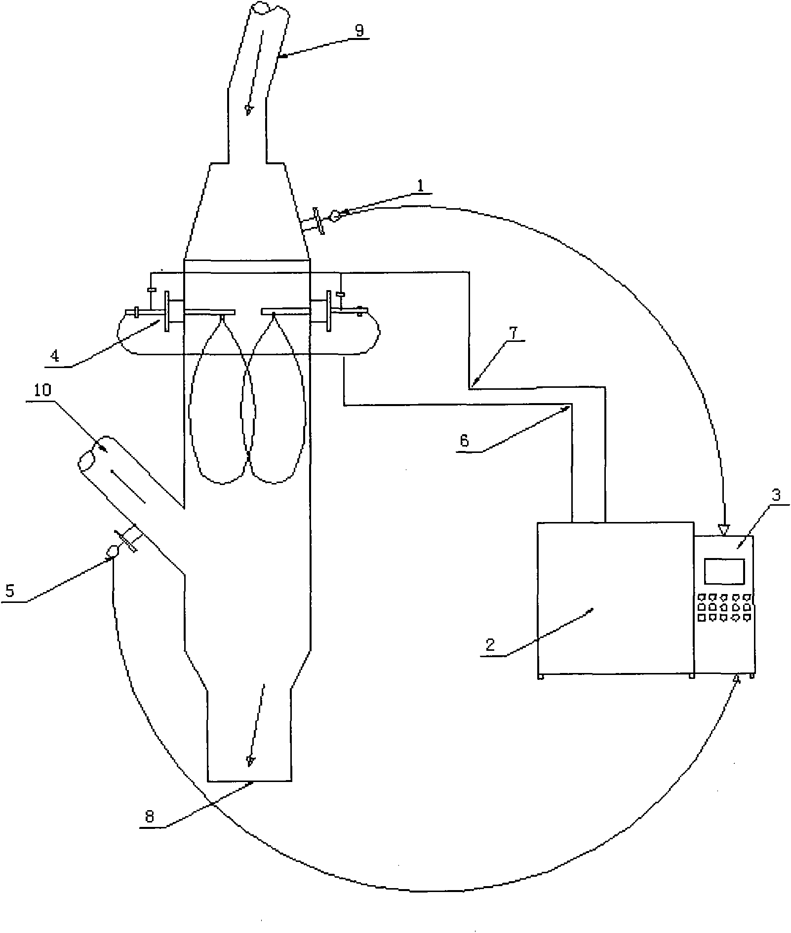
[0017] Example 1 of the high temperature flue gas cooling and tempering equipment is used in the production of cement plants. The flue gas emission requires the outlet temperature of the humidification tower to be maintained within the temperature range of 130°C to 150°C.

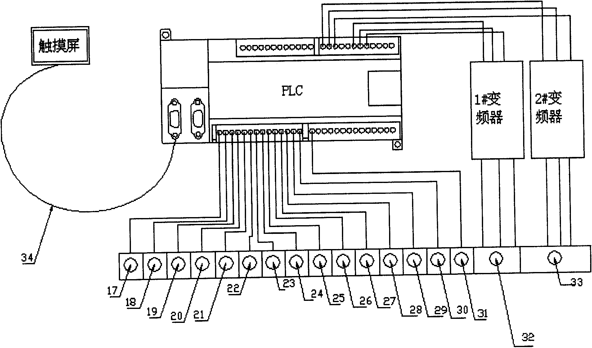
[0018] see figure 1 : The technology of the present invention is the water pipeline 6 and the gas pipeline 7 set between the high temperature flue gas inlet 9 and the outlet 10 of the humidification tower, and the inlet temperature sensor 1 and the outlet temperature sensor 5 are set in the humidification tower, which is characterized in that the gas pipe Set low pressure pump in way 7, see Figure 4 : Gas outlet valve 36, gas shut-off valve 42, gas pressure sensor 41, electromagnetic flowmeter 40, gas hand valve 43 and solenoid valve 44, detection instrument with water pressure sensor 37, control system PLC and inverter are installed in dual The fluid spray cooling control cabinet 39 implements the progr...


PUM


Abstract

The invention discloses a quenching and tempering device for cooling high-temperature fume, comprising a two-fluid electrical appliance controller, a water path and an air path arranged between a high-temperature fume inlet and a high-temperature fume outlet. The device of the invention is characterized in that a low pressure pump is arranged in the air path, a low pressure air path is combined into a water pipeline before a spray gun, two transducers are arranged to adjust the pressure and flow of a water pump and an air pump, the nozzle bore diameter is phi 6-7mm, and the spray particle diameter is smaller than 300 micrometers; a temperature sensor is respectively arranged at a wetting tower inlet and the fume outlet, and the outlet temperature is controller to 130-150 DEG C; an operation program is controlled to calculate the temperature difference of the fume inlet temperature and the fume outlet temperature, tower volume and spray fall height; two transducers are used for controlling the water pump and the air pump to automatically adjust operation power when low air pressure is 0.4-0.6MPa, and air flow quantity and water flow quantity are 5-25T/H. the particle diameter of sprayed water spray is small and even, which can better realize precise control to temperature and reduces atomization particle residence time and wet bottom danger. The dust removal device designed by the invention increases fume density and volume, lowers speed and improves dust removal function. In particular, the spray granularity is small, which can obviously control temperature and humidity, lower discharge Dioxin and furan mixed in dust and reduce environment protection cost.

Description

technical field [0001] The invention relates to a treatment facility for discharging flue gas, and a high-temperature flue gas cooling and tempering device. Background technique [0002] At present, the high-temperature flue gas cooling equipment on the market basically uses high-pressure water, through special nozzles, and relies on the ultra-high pressure of water to perform atomization. This kind of equipment has short lifespan, high failure rate, low efficiency of high pressure pump and high energy consumption. Pressure changes lead to unstable performance and poor atomization effect. The spray diameter is 300-600 microns, and the longer residence time is likely to cause wet bottom. Due to the uneven size of spray particles and the lack of effective control measures for temperature and humidity, dust is likely to be discharged with the flue gas, affecting the dust removal effect. If the amount of flue gas increases, the cooling system equipment must be expanded, and ma...

Claims


Application Information

Patent Timeline
Patent Type & Authority Applications(China)
IPC IPC(8): B01D51/00B01D51/10F28C1/02F28F27/00
CPCY02B30/748Y02B30/70
Inventor 刘春宇
Owner SHENYANG XINCHENG TECH
Why Eureka
Try Eureka