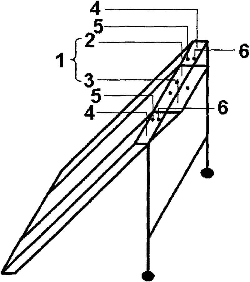
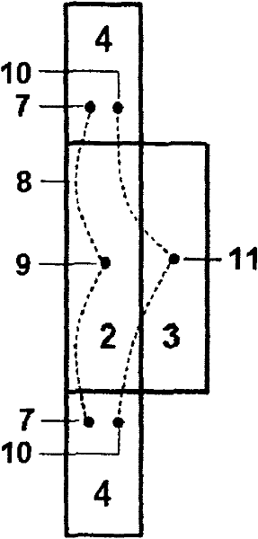
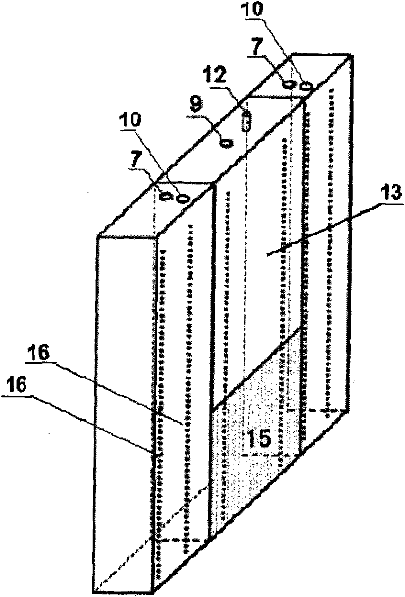
Device for producing hydrogen through decomposing water

A hydrogen production device and water splitting technology, applied in the electrolysis process, electrolysis components, cells, etc., can solve the problems of low efficiency, not conducive to the full use of sunlight, and difficult separation of hydrogen and oxygen, so as to avoid reverse reactions and improve the utilization rate of solar energy , The effect of saving the cost of hydrogen production

Active Publication Date: 2011-09-07
ENN SCI & TECH DEV
View PDF1 Cites 2 Cited by
  • Summary
  • Abstract
  • Description
  • Claims
  • Application Information

AI Technical Summary

Problems solved by technology

Since sunlight reaches the solar cell through the photoanode of the photoelectrochemical cell, this system is not conducive to fully utilizing sunlight
[0007] Therefore, it is of great significance to develop a solar water splitting hydrogen production device that overcomes the low efficiency of semiconductor photocatalytic hydrogen production and the difficulty of separating hydrogen and oxygen, solves the cost problem of photoelectrochemical hydrogen production, and at the same time improves the utilization rate of sunlight.

Method used


Image

  • Device for producing hydrogen through decomposing water
  • Device for producing hydrogen through decomposing water
  • Device for producing hydrogen through decomposing water

Examples


preparation Embodiment 1

[0029] Preparation Example 1 (PEC photoanode (WO 3 Preparation of film samples))

[0030] A metal tungsten sheet with a thickness of about 1mm was placed in a tube furnace (OTF-1200X, Hefei Kejing Material Technology Co., Ltd.), and burned at 810 °C for 15 minutes in an oxygen atmosphere to form a layer of thickness on its surface. WO of about 1.5 μm 3 Oxide film, take it out for use.

preparation Embodiment 2

[0031] Preparation Example 2 (PEC photoanode (carbon-doped TiO 2 Preparation of film samples))

[0032] Carbon-doped TiO using a magnetron sputtering apparatus (Beijing Chuangshi Chengna Technology Co., Ltd.) 2 Preparation of thin film samples. CO in a volume mixing ratio of 1:5:9 2 , O 2 A fluorine tin oxide (FTO) substrate was sputter-coated using a Ti target in a mixed gas atmosphere with Ar. The substrate temperature was maintained at 400°C, and sputtering was performed at a power of 300 watts for 2 hours so that the thickness of the sputtered layer was 500 nm. The sample is then removed for use.

preparation Embodiment 3

[0033] Preparation Example 3 (Preparation of Dye-Sensitized Cell)

[0034] 9cm in area 2 A layer of TiO with a thickness of 2um and a particle size of 20nm was scraped on the FTO substrate. 2particle layer. Then, the FTO substrate was immersed in an ethanol solution of N719 dye (Dalian Seven Colors Light Solar Technology Development Co., Ltd.) with a concentration of 20 mg / L, and was taken out to dry at room temperature after 24 hours. The above-treated FTO substrate was used as a photoanode. Set another area to 9cm 2 The FTO substrate was pulled in an aqueous solution of chloroplatinic acid with a concentration of 0.01 mol / L using a pulling machine (TL0.01, Shenyang Kejing Equipment Manufacturing Co., Ltd.), and then in a muffle furnace (SX-4-10 , Tianjin Test Instrument Co., Ltd.) for 2 h to form a Pt layer with a thickness of 200 nm on the FTO substrate. The FTO substrate was used as a counter electrode. The dye side of the photoanode and the Pt side of the counter el...


PUM

PropertyMeasurementUnit
thicknessaaaaaaaaaa

Abstract

The invention relates to a device for producing hydrogen through decomposing water, which comprises a photoelectrochemical cell including an optical anode and an optical cathode, and a solar cell which is used for generating voltage bias and includes an anode and a cathode, wherein the solar cell is electrically connected with the photoelectrochemical cell; the optical anode of the photoelectrochemical cell and the solar cell are arranged in the incident plane of sunshine. The device of producing hydrogen through decomposing water can overcome the problems of lower efficiency and hard hydrogen-oxygen separation during preparing hydrogen through semiconductor photocatalysis, solve the cost problem of photoelectrochemical hydrogen production, and simultaneously improve the operating factorsof sunshine.

Description

technical field [0001] The invention relates to a device for producing hydrogen by splitting water, in particular to a device for producing hydrogen by splitting water without external bias. Background technique [0002] In the past researches on hydrogen production from water splitting by sunlight, there are mainly two methods, one is semiconductor photocatalytic hydrogen production, and the other is photoelectrochemical hydrogen production. [0003] Semiconductor photocatalytic hydrogen production is one of the commonly used methods for hydrogen production from water splitting by sunlight. Generally, semiconductor particles with suitable bandwidth are used as carriers, and materials with high hydrogen evolution activity (such as Pt, Rh, etc.) are used as carriers to deposit on the semiconductor particles, and then the semiconductor photocatalytic reaction is carried out under illumination. Semiconductor particles (e.g. TiO 2 , ZnO 2 etc.) have an energy band structure, ...

Claims


Application Information

Patent Timeline
Patent Type & Authority Patents(China)
IPC IPC(8): C25B1/04C25B9/04
CPCY02E70/10Y02E60/366Y02E60/36Y02P20/133
Inventor 郑善亮赵伟沈晓彦周祥勇段晓菲丁哲波甘中学
Owner ENN SCI & TECH DEV
Why Eureka
Try Eureka