
Gas liquefying process for mixed refrigerant and mixed refrigerant

A technology of mixing refrigerants and refrigerants, applied in refrigeration and liquefaction, gas/liquid distribution and storage, liquefaction, etc., can solve the problems of long start-up time, many units, abnormal operation, etc., to achieve flexible load adjustment, safe and reliable operation , The effect of load adjustment is convenient

Inactive Publication Date: 2011-08-17
LIAONING CIMC HASHENLENG GAS LIQUEFACTION EQUIP CO LTD
View PDF6 Cites 3 Cited by
  • Summary
  • Abstract
  • Description
  • Claims
  • Application Information

AI Technical Summary

Problems solved by technology

[0006] (2) There are many units, many ancillary equipment, complex pipelines and control systems
[0010] (2) The management technology requirements are high, it is difficult to properly mix the mixed refrigerant, and the start-up time is long. When the gas volume and air pressure of the gas source change greatly, the proportion of the mixed refrigerant needs to be recalculated and adjusted accordingly
[0013] (2) Large energy consumption, large heat exchange area, and large investment in equipment metal
[0016] In the above process, the refrigerant is composed of at least five components, and contains heavy hydrocarbon components above C4. Correspondingly, the proportion of the refrigerant is relatively complicated, and more equipment space is required for storage. The heavy hydrocarbon components contained have a great impact on the operating parameters. , compressors and other equipment have relatively high requirements, and are prone to abnormal operation and damage to the compressor

Method used


Image

  • Gas liquefying process for mixed refrigerant and mixed refrigerant
  • Gas liquefying process for mixed refrigerant and mixed refrigerant

Examples


Embodiment 1

[0033] [Example 1] Coalbed methane liquefaction

[0034] Purified coalbed methane components after deacidification and dehydration (mole percentage): nitrogen 2.0843% methane 97.901% ethane 0.0053% propane 0.0001% other 0.0093%, pressure: 4.46 MPa, temperature: 38°C.

[0035] CBM liquefaction process:

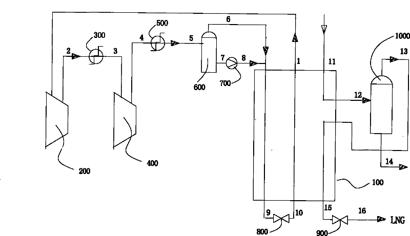
[0036] The purified bed gas 11 enters the cold box 100 for pre-cooling, and the coal bed gas 12 that is pre-cooled to -70°C exits the cold box and enters the heavy hydrocarbon separator 1000. The heavy hydrocarbon 14 is discharged from the bottom of the heavy hydrocarbon separator, and its flow is zero, that is, there is no heavy hydrocarbon. Precipitation. The gas phase 13 from the top of the heavy hydrocarbon separator enters the cold box 100 for deep cooling. The supercooled liquid 15 cooled to -150℃ exits the cold box, and the pressure is reduced to 0.4MPa by the throttle valve 800, and the low pressure supercooled liquid 16 enters the LNG Storage unit.

[0037] Refrigerant cycl...

Embodiment 2

[0040] [Example 2] North Sea Natural Gas Liquefaction

[0041] Purified natural gas components (mol %) after deacidification and dehydration: nitrogen 1.5%, methane 77%, ethane 14.5%, propane 3%, n-hexane 4%, pressure: 4.97 MPa, temperature: 38°C.

[0042] CBM liquefaction process:

[0043] The purified bed gas 11 enters the cold box 100 for pre-cooling, the coal bed gas 12 pre-cooled to -35° C. exits the cold box and enters the heavy hydrocarbon separator 1000, and the heavy hydrocarbon 14 is discharged from the bottom of the heavy hydrocarbon separator. The gas phase 13 from the top of the heavy hydrocarbon separator enters the cold box 100 for deep cooling, and the supercooled liquid 15 cooled to -140℃ exits the cold box, throttling down to 0.6MPa through the throttle valve 800, and the cryogenic liquid 16 enters the LNG storage unit .

[0044] Refrigerant cycle process:

[0045] 31℃ low-pressure gaseous mixed refrigerant 1 exits the cold box 100 and enters the refrigeration first...

Embodiment 3

[0047] [Example 3] Jilin Natural Gas Liquefaction

[0048] Purified CBM components after deacidification and dehydration (mol %): nitrogen 3.42%, methane 94.55%, ethane 1.22%, propane 0.09%, butane 0.37%, n-pentane 0.18%, other 0.17%, pressure: 3.97MPa , Temperature: 38℃.

[0049] Weather liquefaction process:

[0050] The purified bed gas 11 enters the cold box 100 for pre-cooling, the coal bed gas 12 pre-cooled to -70°C exits the cold box and enters the heavy hydrocarbon separator 1000, and the heavy hydrocarbon 14 is discharged from the bottom of the heavy hydrocarbon separator. The gas phase 13 from the top of the heavy hydrocarbon separator enters the cold box 100 for deep cooling, and the supercooled liquid 15 cooled to -156°C is discharged from the cold box, and the pressure is reduced to 0.12MPa through the throttle valve 800, and the cryogenic liquid 16 enters the LNG storage unit .

[0051] Refrigerant cycle process:

[0052] 30℃ low-pressure gaseous mixed refrigerant 1 e...


PUM


Abstract

The invention relates to a gas liquefying process for mixed refrigerant, which comprises the following steps: providing the mixed refrigerant which comprises the following components in percentage by mole: 5 to 10 percent of nitrogen, 30 to 40 percent of methane, 5 to 10 percent of ethylene, and 45 to 60 percent of propane; feeding the mixed refrigerant to a single refrigerant circulating system to carry out closed cycle to produce cold energy required by cooling gas; and exchanging heat of the gas needing to be liquefied and the refrigerant circulating system through a gas liquefying system so that the gas is cooled and liquefied. The process flow is simple, the components of the refrigerant are reasonable, and a liquefying device has the advantages of safe and reliable operation, simplework, flexible load adjustment and low energy consumption.

Description

Technical field [0001] The invention relates to a gas liquefaction process. [0002] The invention also relates to the mixed refrigerant used in the liquefaction process. Background technique [0003] The liquefied natural gas liquefaction process mainly includes three forms: cascade liquefaction process, mixed refrigerant liquefaction process, and liquefaction process with expander: [0004] The cascade liquefaction process consists of three independent refrigeration cycles, the refrigerants are propane, ethylene and methane. The first-stage propane refrigeration cycle provides refrigeration for natural gas, ethylene and methane; the second-stage ethylene refrigeration cycle provides refrigeration for natural gas and methane; the third-stage methane refrigeration cycle provides refrigeration for natural gas. Through the cooling of the heat exchanger, the temperature of natural gas is gradually reduced until it is liquefied. The main features of this process are: [0005] (1) The e...

Claims


Application Information

Patent Timeline
Patent Type & Authority Patents(China)
IPC IPC(8): F25J1/02F25B9/00C09K5/00F17C5/04
CPCF25J1/0212F25J1/0022F25J1/0052F25J1/0092F25J2220/64F25J2235/60
Inventor 刘勇屠光宗
Owner LIAONING CIMC HASHENLENG GAS LIQUEFACTION EQUIP CO LTD
Learn More