Automobile hydraulic electric power steering reliability test bench and program control test method

A technology of hydraulic power steering and test bench, which is applied in the direction of vehicle steering/bumping performance, etc. It can solve the problems that there is no road surface uneven vibration simulation system, and the performance test of the input terminal cannot be passed, so as to achieve compact space occupation, small occupation space and low requirements Effect

Inactive Publication Date: 2009-12-23
SICHUAN UNIV
2 Cites 19 Cited by

AI-Extracted Technical Summary

Problems solved by technology

[0003] Chinese patent application: 'automobile steering gear assembly variable load test bench system' patent application number: 02109786.0, the load size is completed by the loading box at the input end of the steering gear, and the loading box simulates the torque force of the tire through a torsion spring. The simulation is not suitabl...

Method used

See Fig. 7, hydraulic system 15 establishes steering gear circuit 15A and output hydraulic circuit 15B, is respectively provided with oil tank 15.1a and 15.1b, filter 15.2a and 15.2b, hydraulic pump 15.3a and 15.3b, Relief valves 15.4a and 15.4b, reversing valves 15.5a and 15.5b, throttle valves 15.6a and 15.6b (two), pressure gauges 15.7a and 15.7b. The steering gear circuit is equipped with a flow meter 15.8a and an oil pressure transmitter 14.9 for collecting oil pressure to directly communicat...

Abstract

The invention relates to an automobile hydraulic electric power steering reliability test bench and program control test method. An input system comprises a servo motor, a reducer and a universal joint connected with the input end of a steering gear; an output system comprises a linear hydraulic cylinder with two functions of driving and load simulation, the front pole of a hydraulic cylinder piston is provided with a pressure sensor and connected with the rocker arm of the output end of the steering gear by a coupler with a joint bearing. An eccentric shaft, an eccentric bushing and a variable frequency motor are arranged at the inner bore of the rear lug of the hydraulic cylinder to form an automobile vibration simulation system, so as to simulate real vibration of rugged road surface. The hydraulic cylinder is compact and simple in structure, system integration is high and usable range is wide. The joint bearing causes the installation to be convenient. The hydraulic loop includes a throttle valve, thus speeding up oil-taking. An industrial personal computer, a motion control card and a data acquisition card are used, so that system stability is high, measurement accuracy is high, and response speed is fast. Curves and process control can be displayed in real time, and automatic save, plotting and printing can be realized. The test bench set can complete all reliability tests of fatigue, wear, forced steering, inverse overload and overpressure.

Application Domain

Vehicle steering/rolling behaviour

Technology Topic

Image

  • Automobile hydraulic electric power steering reliability test bench and program control test method
  • Automobile hydraulic electric power steering reliability test bench and program control test method
  • Automobile hydraulic electric power steering reliability test bench and program control test method

Examples

  • Experimental program(1)

Example Embodiment

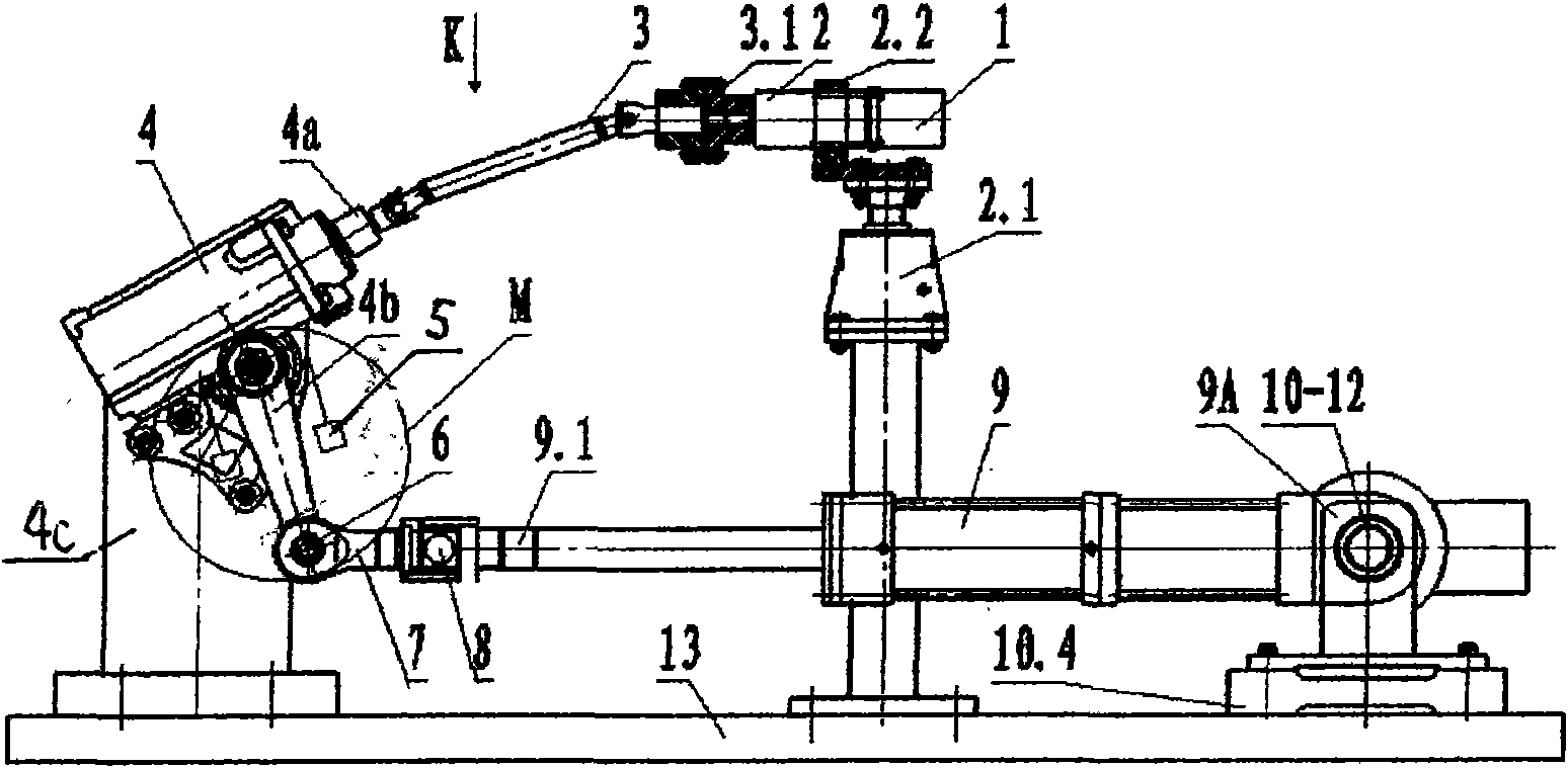
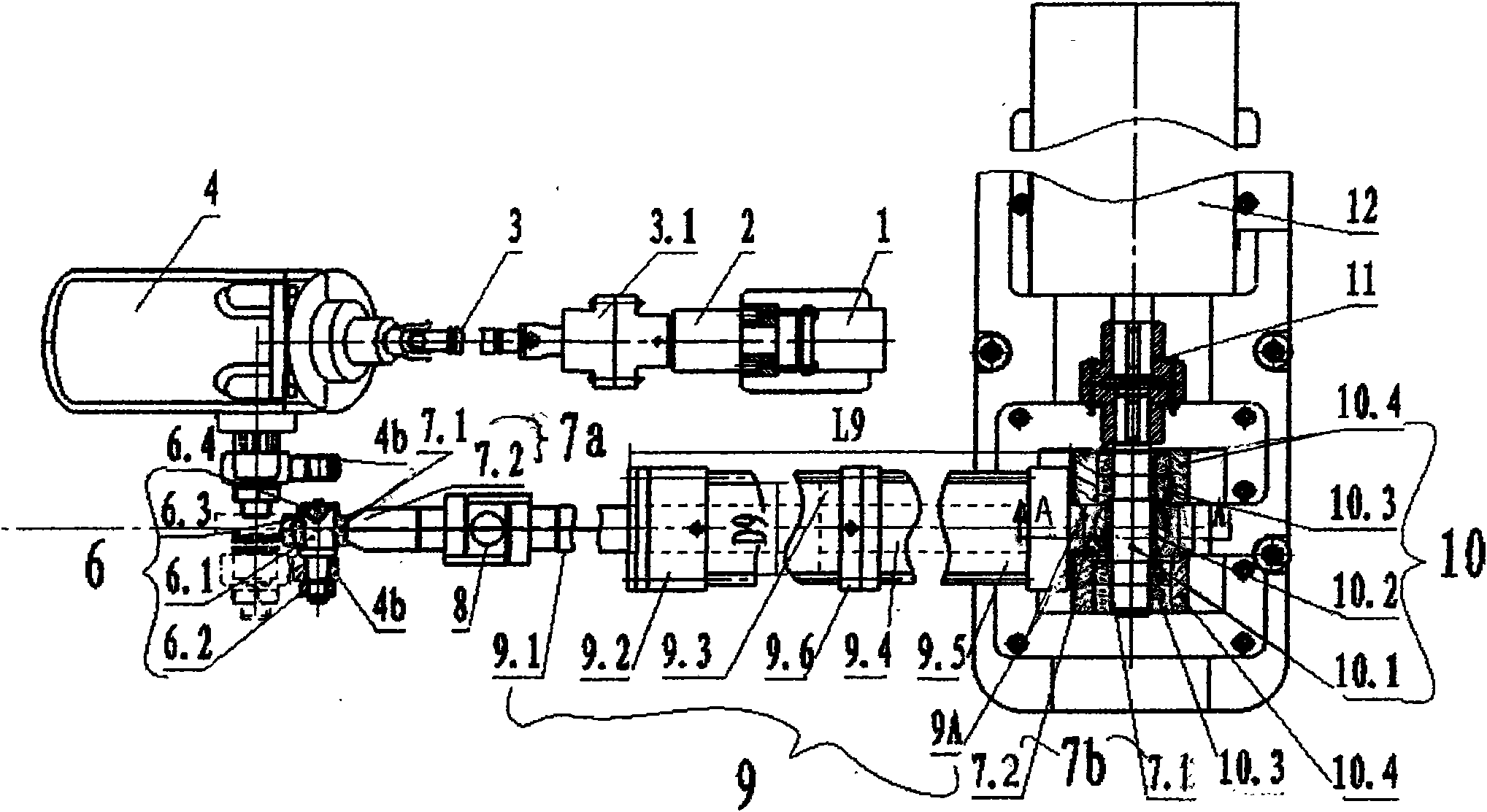
[0031] The reliability test bench of the automobile hydraulic power steering gear of this embodiment is formed as follows:
[0032] see figure 1 , figure 2 , The input system is provided with a servo motor 1, a reducer 2 and a universal joint 3 which are connected in sequential transmission; the output end of the universal joint is connected with the input end 4a of the steering gear 4. The steering gear 4 is kept inclined to the horizontal direction, which is similar to the original car installation method, which can meet the variety of test product models. The outer circumference of the reducer is covered with a mounting plate 2.2 fixed to the upper end of the worm gear screw elevator 2.1, and the lower end of the elevator is fixed to the foundation table 13 of the test bench. Therefore, the servo motor and the reducer are installed on the lifting table, and the height can be adjusted arbitrarily. The reducer and the universal joint are connected with a universal-reduction coupling 3.1. The diverter 4 is supported and fixed to the base platform 13 with a mounting fixture 4c (ie, a bracket 4c), and the base platform adopts a T-shaped groove to install the base platform. The output end of the steering gear is equipped with a limit stop 5, which is placed at both ends of the rocker arm. It is an electronic component and is installed on a fixed fixture. This limit stop 5 is not used frequently and will affect other tests. , So when needed in the system design process, temporarily install it to control the rocker arm 4 at the output end of the steering gear b Rotation.
[0033] see figure 1 , figure 2 , The output system is equipped with a double-acting linear hydraulic cylinder 9; it is composed of a front oil cylinder 9.2 and a rear isolation chamber 9.5, with a sealing isolation plate 9.6 in the middle; inside the oil cylinder 9.2 there are piston front rods 9.1 and 9.1 that are fixed to the piston 9.3 and extend forward from the oil cylinder. The piston rear rod 9.4 extending backward to the isolation chamber. The front end of the piston rod is equipped with a pull pressure sensor 8. see figure 2 , Figure 4 , The first joint bearing 7a at the front end of the tension pressure sensor is composed of a bearing jacket 7.2 and a hollow ball 7.1 in the jacket; the shaft 6.1 of the coupling 6 passes through the inner hole of the rocker arm 4b and the inner hole of the hollow ball 7.1 at the same time, with a retaining ring 6.4 at one end It is fixed with bolts 6, 3, and the other end is tightened with a nut 6.2, then the front end of the piston of the hydraulic cylinder is connected with the rocker arm 4b of the steering gear. The maximum working oil pressure of the steering gear circuit design is 20MPa, and the average working oil pressure is 13.7MPa, see figure 2 , Double-acting linear hydraulic cylinder diameter D 9 Take 80mm, hydraulic cylinder length L 9 Take 760mm. The design is based on the reciprocating frequency of the hydraulic cylinder being 0.5~1.2Hz, the flow rate of the steering gear is 16L/min, according to the formula: flow per second T=π×(D 9 /2) 2 , The diameter of the hydraulic cylinder D is obtained by calculation 9 It is 80mm. see image 3 According to the test, the swing angle amplitude of the rocker arm is 90°(45+45), the arm length L=250mm, and the linear hydraulic cylinder stroke is S. According to the formula: S=L/Sin45°, S=350mm is calculated, Taking into account the actual situation, the design stroke is 500mm. Considering that the linear hydraulic cylinder has a dual-axis dual-extension design, the cylinder body is lengthened, and L9 is taken as 760mm.
[0034] see figure 1 , figure 2 , Figure 4 with Figure 5 , Double-acting linear hydraulic cylinder 9 cylinder body rear ear inner hole 9A passes through an eccentric shaft 10.1, the shaft is equipped with an eccentric sleeve 10.2, the eccentric sleeve is fixedly installed on the eccentric shaft, so that the two cannot rotate relative to each other; in the eccentric sleeve 10.2 A second joint bearing 7b is installed between the inner ear hole 9A, and its hollow ball 7.1 inner hole is sleeved outside the eccentric sleeve 10.2, and the second joint bearing outer ring 7.2 is installed in the ear inner hole 9A. Both ends of the eccentric shaft are equipped with supported double row radial ball bearings 10.3, and the bearing seat 10.4 is installed on the foundation table 13. One end of the eccentric shaft 10.1 is connected to the output shaft of the variable frequency motor 12 through a variable-deflection coupling 11. see Figure 4 , The eccentric sleeve 10.2 inner hole diameter and outer circle diameter center distance Δ is 1mm. The eccentric vehicle simulation vibration system is formed by the above structure.
[0035] see Figure 6 , The solid line represents the mechanical connection, and the dashed line represents the control signal. The electronic control system 14 is formed as follows: (1) There is an industrial computer 14.4 and system software. ②The MPC motion control card 14.3 controls the servo motor 1 in the industrial computer. ③Set the motion control expansion card 14.6 to control the three-position three-way solenoid valve 14.7 of the double-acting linear hydraulic cylinder 9 oil circuit (that is, Figure 7 The reversing valve 15.5b) and the two-position four-way solenoid valve 14.8 of the steering gear circuit (that is, the Figure 7 The middle reversing valve 15.5a); the two solenoid valves 14.7 and 14.8 pipelines are respectively driven by the pump drive motors 14.10 and 14.11 to circulate the oil with the hydraulic pump of the hydraulic station. ④The data acquisition card 14.2 selects Advantech PCL818L type, directly collects the pressure of the pull pressure sensor and collects the pressure of the steering gear 4 loops through the pressure transmitter 14.9; and controls the frequency converter 14.1 of the variable frequency motor 12 through the data acquisition card 14.2 Up to VFD037B43A). The data acquisition card 14.2 provides data to the industrial computer through the ISA interface.
[0036] see Figure 7 The hydraulic system 15 is equipped with a steering gear circuit 15A and an output hydraulic circuit 15B. The two circuits are respectively equipped with oil tanks 15.1a and 15.1b, filters 15.2a and 15.2b, hydraulic pumps 15.3a and 15.3b, overflow valve 15.4a and 15.4b, reversing valves 15.5a and 15.5b, throttle valves 15.6a and 15.6b (two), pressure gauges 15.7a and 15.7b. The steering gear circuit is equipped with a flow meter 15.8a and an oil pressure transmitter 14.9 for collecting oil pressure directly connected to the working cavity of the steering gear 4, and a cooler 15.9a for cooling circulating oil is required. The output hydraulic circuit is equipped with a speed control valve 15.8b at the inlet end of the reversing valve 15.5b. Two throttle valves 15.6b are provided in the output hydraulic circuit with the reversing valve 15.5b to realize two-way oil intake to ensure continuous oil circulation, test performance and smooth completion when the output system is under load.
[0037] see Figure 8 , Electronically controlled manual part 16. AC 380V one-phase lead is grounded to form a 220V AC power supply. KM1~KM5 are contactors, which are controlled by switches. The contactors are energized to start the corresponding equipment 16.1~16.9. The contactors are equipped with self-locking, and the button can automatically record the status. In the picture: SB6~SB7 are self-locking buttons with green light L6. SB1A~SB5A are non-self-locking buttons. SB1B~SB5B are non-self-locking buttons with green light L 1 ~L 5. Equipment 16.1 is a switching power supply; 16.2 is a pump drive motor 14.10; 16.3 is a pump drive motor 14.11; 16.4 is a switching power supply; 16.5 is a hydraulic oil heater (installed in Figure 7 Inside the middle hydraulic cylinder 9); 16.6 is hydraulic air-cooled equipment (installed on the outside of the pipeline of the steering gear hydraulic oil circuit for cooling oil, see Figure 7 Intercooler 15.9a) 16.7 is the frequency conversion motor 12 and drive; 16.8 is the frequency conversion motor fan; 16.9 is the servo motor 1 and drive.
[0038] see Picture 9 , The execution part of automatic control 17. KM10-KM12, KM15-KM16 are relays controlled by motion control expansion card 14.6 (select MPC08), solenoid valve 14.8 (that is, reversing valve 15.5a) is electro-hydraulically started; solenoid valve 14.7 (that is reversing valve 15.5b) left, The right controls the left and right movements of the hydraulic cylinder, and the rest controls the warning light 14.5.
[0039] see Picture 10 , The program-controlled test method adopted by the reliability test bench of automobile hydraulic power steering gear. This method is a synchronous acquisition method of multi-threaded analog quantity using DMA mode; the industrial computer uses computer language to write programs. The program-controlled test method has the following steps: 1) Start 2) Initialization: Simultaneously perform manual control settings including continuous and jog; 3) Automatic detection: including detecting whether the hardware is ready; 3) Test steps: including performing the required five experiments; 4) Performing test actions: setting There is a compensation and correction program used to control the impact force of the double-acting linear hydraulic cylinder 9; 5) Collect data: The set sampling rate is at least 100 times per second; 6) Whether it reaches the extreme value: Determine whether the pressure and torque of the collected data are extreme If the value is not reached, return to the collection data to continue collection; 7) Test completed: determine whether the test is completed; if not, return to the execution of the test action; 8) save the drawing; 9) exit the system; 10) end.
[0040] Some industrial computers are equipped with the following VC++ language programming modules: the main interface module for human-computer interaction; the initialization input module with manual continuous or jog control; used to collect the pressure of the steering gear and the sensor, and control the data of the variable frequency motor Acquisition module; used to control the motion control module of the servo motor and solenoid valve, as well as the graphic display module, the data storage query module and the report output module.

PUM

no PUM

Description & Claims & Application Information

We can also present the details of the Description, Claims and Application information to help users get a comprehensive understanding of the technical details of the patent, such as background art, summary of invention, brief description of drawings, description of embodiments, and other original content. On the other hand, users can also determine the specific scope of protection of the technology through the list of claims; as well as understand the changes in the life cycle of the technology with the presentation of the patent timeline. Login to view more.

Similar technology patents

Adaptive correction method for color gray-scale image of display

ActiveCN102629466AGuaranteed display qualitySmall footprintCathode-ray tube indicatorsImage propertiesCorrection method
Owner:NANJING JUSHA DISPLAY TECH

Classification and recommendation of technical efficacy words

  • Compact footprint
  • Small footprint

Apparatus for irradiation

ActiveUS20140161664A1Compact footprintWater treatment compoundsMaterial analysis by optical meansVisible RadiationsMedical physics
Owner:AQUISENSE TECH

Deep hole machining on-line deviating correction device based on laser detection

ActiveUS9561547B1Good straightness and position accuracyCompact footprintBoring barsMetal working apparatusPrismLaser transmitter
Owner:ZHONGBEI UNIV

Cold press system

PendingCN111153143ACompact footprintEfficient deliveryPlywood pressesVeneer pressesPhysicsEngineering
Owner:珠海市华衍木业有限公司
Why Eureka
Try Eureka