

Method for producing CdS/CdTe solar cell by magnetron sputtering method
A solar cell, magnetron sputtering technology, applied in sputtering plating, circuits, electrical components, etc., can solve the problems of cumbersome, complex process, high cost, and achieve large product area, high film quality and low cost. Effect
- Summary
- Abstract
- Description
- Claims
- Application Information
AI Technical Summary
Problems solved by technology
Method used
Image

Examples
Embodiment 1
[0035] (1) Formation of CdS / CdTe film
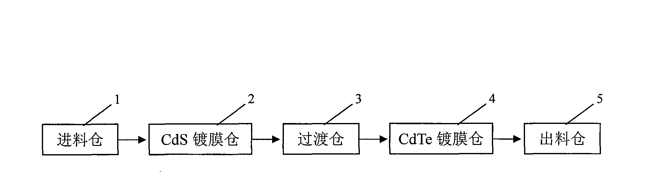
[0036] Put the cleaned and photoetched conductive glass workpiece into the fixture, start the conveying system to send the workpiece into the feeding bin 1, close the bin door, start the vacuum system, and pump to 2.5×10 -2 Pa, start the infrared heater to make the temperature of the workpiece reach 230°C, fill it with argon to 0.5×10 0 Pa, open the door between the preparation bin and the CdS coating bin 2, the workpiece is sent into the CdS bin by the conveying system, close the door between the feeding bin and the CdS coating bin, CdS is plated by magnetron sputtering, and the current Adjust to 4mA / cm 2 , the distance between the target and the workpiece is controlled at 100mm, and the time is 7min, so that the CdS film thickness is 70nm, stop sputtering, open the door of CdS and the transition chamber, start the conveying system to send the workpiece into the transition chamber 3 and fill it with argon, adjust the air pressure to 1...
Embodiment 2
[0044] (1) Formation of CdS / CdTe film
[0045] Put the cleaned and photolithographically completed conductive glass workpiece into the fixture, start the conveying system to send the workpiece into the feeding bin 1, close the bin door, start the vacuum system, and pump to 5.5×10 -2 Pa, start the infrared heater to make the temperature of the workpiece reach 250°C, fill it with argon to 2.2×10 0 Pa, open the door between the preparation bin and the CdS coating bin 2, the workpiece is sent into the CdS bin by the conveying system, close the door between the feeding bin and the CdS coating bin, CdS is plated by magnetron sputtering, and the current Adjust to 10mA / cm 2 , the distance between the target and the workpiece is controlled at 220mm, and the time is 10min, so that the CdS film thickness is 120nm, stop sputtering, open the door of CdS and the transition chamber, start the conveying system to send the workpiece into the transition chamber 3 fill with argon, adjust the ai...
Embodiment 3
[0053] (1) Formation of CdS / CdTe film
[0054] Put the cleaned and photoetched conductive glass workpiece into the fixture, start the conveying system to send the workpiece into the feeding bin 1, close the bin door, start the vacuum system, and pump to 3.5×10 -2 Pa, start the infrared heater to make the temperature of the workpiece reach 240°C, fill it with argon to 1.2×10 0 Pa, open the door between the preparation bin and the CdS coating bin 2, the workpiece is sent into the CdS bin by the conveying system, close the door between the feeding bin and the CdS coating bin, CdS is plated by magnetron sputtering, and the current Adjust to 8mA / cm 2 , the distance between the target and the workpiece is controlled at 150mm, and the time is 8min, so that the CdS film thickness is 100nm, stop sputtering, open the door of CdS and the transition chamber, start the conveying system to send the workpiece into the transition chamber 3 and fill it with argon, adjust the air pressure to ...
PUM
 Abstract
Description
Claims
Application Information