

Method for producing optical film, optical film, polarizing plate and display
A technology of optical film and film method, which is applied in the direction of optics, optical elements, polarizing elements, etc., can solve the problems of peeling deterioration, low production speed, and reduced production speed, so as to reduce the constraints of film production conditions and reduce the delay value. Average, productivity-enhancing effects
- Summary
- Abstract
- Description
- Claims
- Application Information
AI Technical Summary
Problems solved by technology
Method used
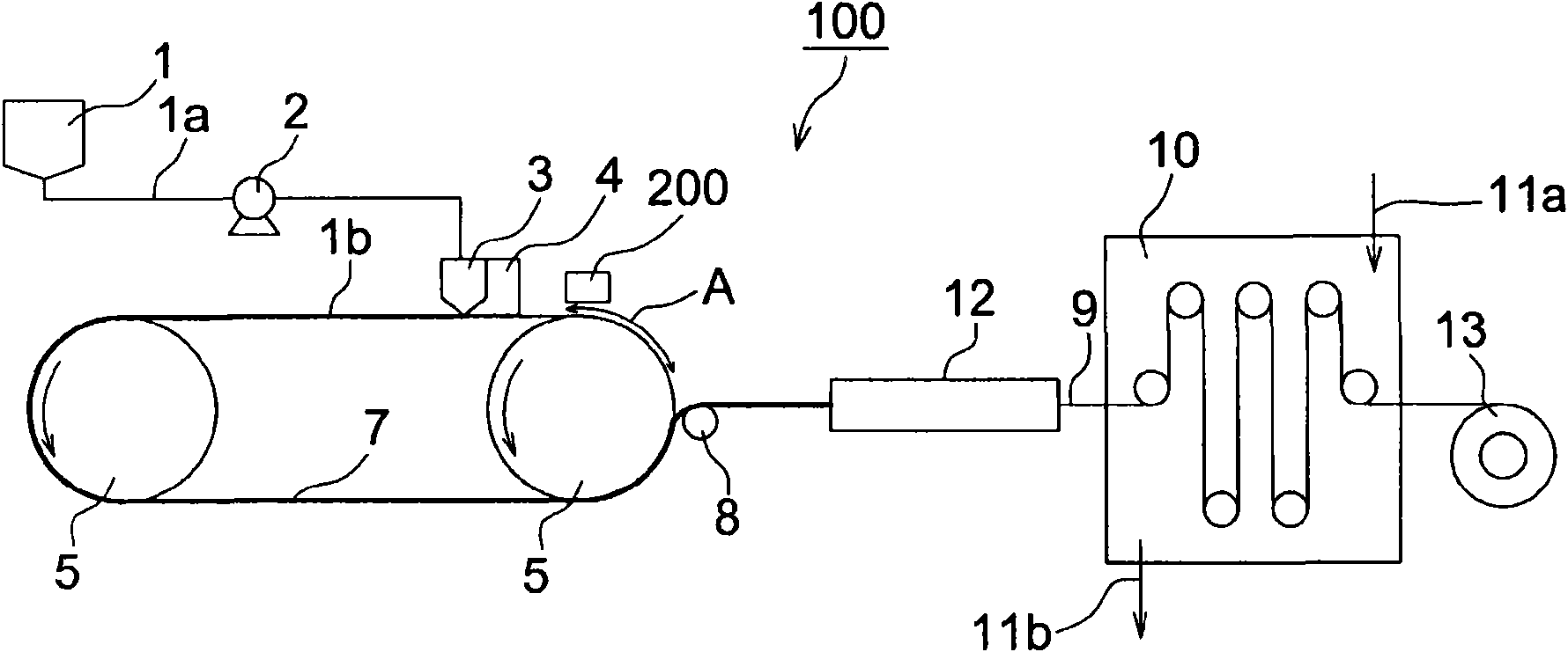
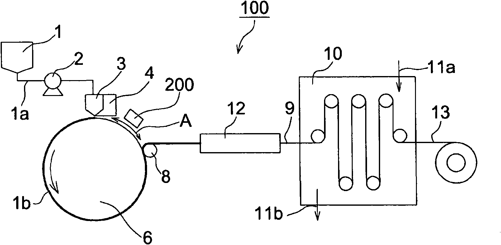
Image

Examples
Embodiment 1
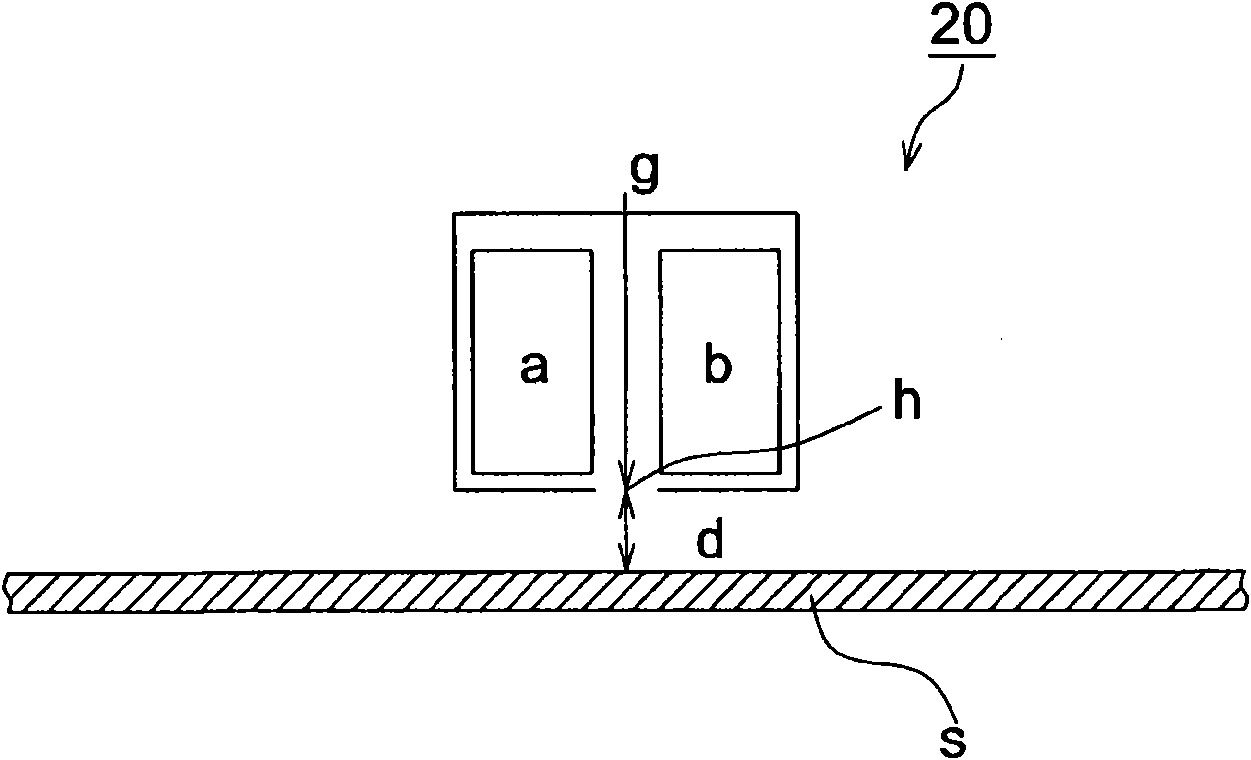
[0300] (atmospheric pressure plasma treatment)
[0301] The gap (d) between the ejection slit (h) of the atmospheric pressure plasma device (20) and the surface of the metal support (s) is set to 2 mm. Under this condition, the metal support (s) is transported while the metal support (s) A plasma irradiation process is performed for 0.0005 seconds by passing under the atmospheric pressure plasma device (20). Since the exact contact time between the free radical and the metal support (s) is difficult to measure, the plasma irradiation time referred to here refers to the time from a certain point on the surface of the metal support (s) from the spray slit (h) Time for the bottom to move across the opening width of the slit (h). For example, if the opening width of the ejection slit (h) is 2 mm and the moving speed of the metal support (s) is 2 mm / sec, the plasma irradiation time is 1 sec. In addition, the amount of reaction gas (g) used is 3m per 1m of irradiation width 3 / mi...
Embodiment 2
[0304] The only difference from Example 1 is that the plasma irradiation treatment time is 0.01 second, and the solvent vapor concentration near the surface of the plasma (s) before entering the atmospheric pressure plasma device (20) is methylene chloride 6500ppm, methanol 1500ppm, others are identical with embodiment 1.
Embodiment 3
[0306] The difference from Example 2 is that 1% by volume of oxygen is added to the reaction gas (g), and the others are the same as in Example 2.
PUM
| Property | Measurement | Unit |
|---|---|---|
| thickness | aaaaa | aaaaa |
| length | aaaaa | aaaaa |
| thickness | aaaaa | aaaaa |
Abstract
Description
Claims
Application Information