Microchannel type photocatalytic microreactor based on nanorod array and preparation method thereof

A nano-rod array and micro-reactor technology, which is applied in the cross-field of nanotechnology, microfluidic technology and photocatalysis technology, can solve the problems of reducing the solid-liquid contact area of ​​catalysts, the difficulty of agglomeration, separation and recovery of nano-catalysts, and large-scale application, achieving The effect of increasing the contact area

Inactive Publication Date: 2010-03-17
DONGHUA UNIV
View PDF0 Cites 19 Cited by
  • Summary
  • Abstract
  • Description
  • Claims
  • Application Information

AI Technical Summary

Problems solved by technology

[0003] Using semiconductor nanomaterials such as TiO 2 , ZnO and other photocatalytic degradation of organic pollutants and photo-splitting of water have attracted research interest (Appl.Catal.B 2000, 26:207-215, Powder Technol.2009, 189:426-432), however, in practical applications , the agglomeration of nanocatalysts and the difficult...

Method used


Image

  • Microchannel type photocatalytic microreactor based on nanorod array and preparation method thereof
  • Microchannel type photocatalytic microreactor based on nanorod array and preparation method thereof
  • Microchannel type photocatalytic microreactor based on nanorod array and preparation method thereof

Examples


preparation example Construction

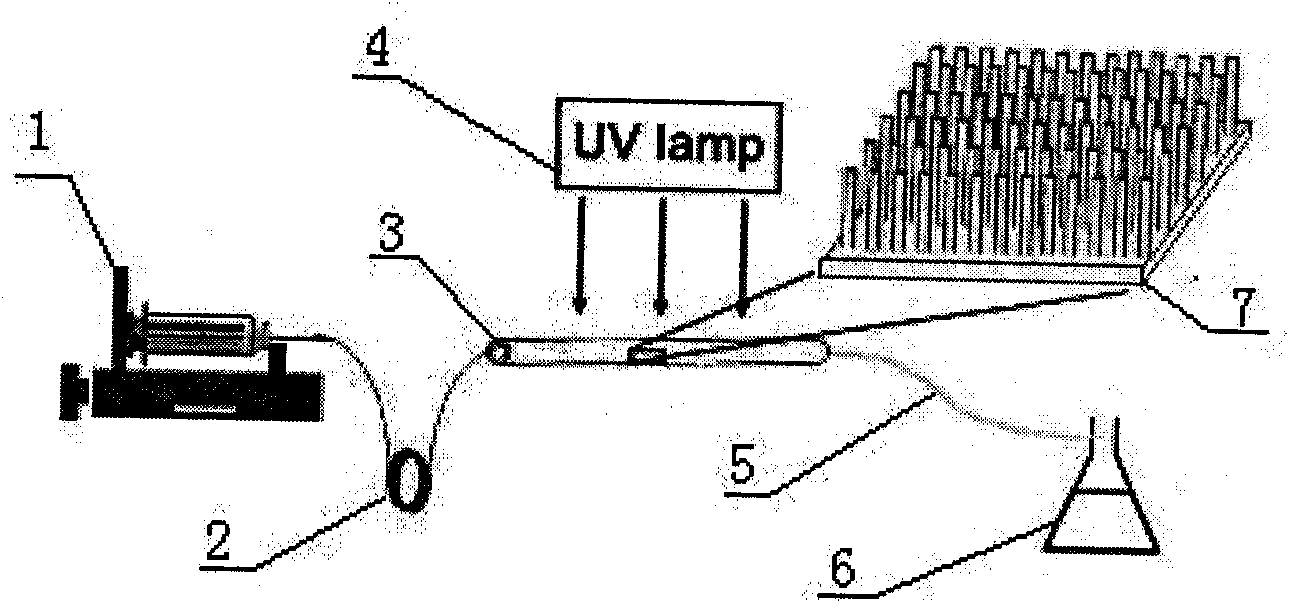
[0032] Embodiments of the present invention also relate to a preparation method of a microchannel photocatalytic microreactor based on a nanorod array, comprising the following steps: (1) selecting a quartz capillary as the microchannel in the photocatalytic zone; Prepare vertically grown semiconductor nanorod arrays on the surface as photocatalysts; (3) take two polytetrafluoroethylene microtubes as fluid delivery channels, and seal them to one end of the quartz capillary with epoxy resin, and then take a polytetrafluoroethylene The microtube is used as a fluid receiving channel, and is sealed to the other end of the quartz capillary with epoxy resin; (4) Two polytetrafluoroethylene microtubes used as fluid delivery channels are respectively connected to two syringes placed on the microinjection pump , place the UV lamp directly above the horizontally placed quartz capillary, and place the fluid receiver at the polytetrafluoroethylene microtube as the fluid receiving channel. ...

Embodiment 1

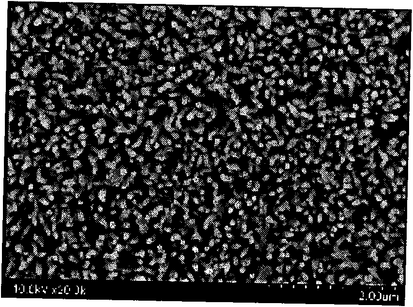
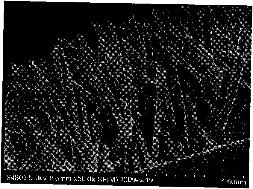
[0036] Example 1: Measure a quartz capillary with a length of 20 cm, an inner diameter of 530 μm, and an outer diameter of 660 μm with a ruler. ZnO nano-seeds were prefabricated on the inner surface of the quartz capillary microchannel by traditional liquid-phase chemical method, and then vertically grown ZnO nanorod arrays were prepared on the inner surface. figure 2 and image 3 For the field emission scanning electron microscope photo of the ZnO nanorod array on the microchannel inner surface that the present embodiment obtains, it can be seen that: the ZnO nanorod array vertically grows on the microchannel inner surface ( image 3 ), and evenly distributed ( figure 2 ). Then take two polytetrafluoroethylene microtubes with an inner diameter of 300 μm and a length of 80 cm as fluid delivery channels, and seal them to one end of the quartz capillary with epoxy resin, and then take another polytetrafluoroethylene microtube with an inner diameter of 800 μm and a length of ...

Embodiment 2

[0037] Example 2: Measure a quartz capillary with a length of 10 cm, an inner diameter of 550 μm, and an outer diameter of 700 μm with a ruler. ZnO nano-seeds were prefabricated on the inner surface of the quartz capillary microchannel by traditional liquid-phase chemical method, and then a vertically grown ZnO nanorod array was prepared on the inner surface, and TiO was introduced into the microchannel with the ZnO nanorod array. 2 nanosol and dried to obtain TiO 2 ZnO coated with nanoparticles, namely ZnO / TiO 2 nanorod arrays. Figure 5 The coupled semiconductor ZnO / TiO on the inner surface of the microchannel obtained in this embodiment 2 Field emission scanning electron microscope photograph of the nanorod array, it can be seen that compared with pure ZnO nanorods, TiO 2 The surface of the coated nanorods becomes slightly rougher and the diameter becomes slightly larger. Then take two polytetrafluoroethylene microtubes with an inner diameter of 400 μm and a length of 8...


PUM

PropertyMeasurementUnit
The inside diameter ofaaaaaaaaaa
Outer diameteraaaaaaaaaa
Lengthaaaaaaaaaa

Abstract

The invention relates to a microchannel type photocatalytic microreactor based on a nanorod array and a preparation method thereof. The photocatalytic microreactor uses a quartz capillary as a photocatalytic region microchannel, uses a semiconductor nanorod array which vertically grows on the inner surface of the microchannel as a photocatalyst, uses a polytetrafluoroethylene micropipe as a fluidconveying and receiving channel, uses an ultraviolet lamp as a light source, and uses a micro-injection pump to convey organic substances into the microchannel, thereby achieving the purpose of continuous, quick and efficient photocatalytic degradation of the organic substances. By adjusting the pushing speed of the micro-injection pump, the complete degradation of the organic substances is realized; and moreover, the microchannel type photocatalytic microreactor still has high photocatalytic activity after being continuously used for 100 hours, and the degradation rate for the organic substances is still more than 80%.

Description

technical field [0001] The invention relates to the interdisciplinary field of nanotechnology, microfluidic technology and photocatalysis technology, in particular to a microchannel photocatalytic microreactor based on nanorod arrays. Background technique [0002] Since the 1990s, an important trend in the development of natural science and engineering technology is to move towards miniaturization. In order to adapt to this development trend, in 1990, Manz A. of the analytical laboratory of Ciba-Geigy Company in Switzerland proposed the microreactor. concept. As a new technology, microreactor has the characteristics of high efficiency, rapidity, flexibility, easy control, easy direct amplification and high integration compared with traditional chemical reactors. It can realize on-site, on-demand production and supply without Storage and transportation, improving safety, and making full and reasonable use of scattered resources are of great significance to environmental safe...

Claims


Application Information

Patent Timeline
IPC IPC(8): B01J19/00B01J19/12B01J35/02
Inventor 王宏志何中媛李耀刚张青红
Owner DONGHUA UNIV
Why Eureka
Try Eureka