Spin Microwave Oscillators and Spin Microwave Detectors
A technology of detectors and oscillators, applied in resonators, waveguide devices, instruments, etc., can solve the problems of narrow frequency modulation range, difficulty in integration, difficulty in frequency modulation, etc., achieve high frequency controllable tunability, simplify device structure and Process, improve the effect of radiation resistance
- Summary
- Abstract
- Description
- Claims
- Application Information
AI Technical Summary
Problems solved by technology
Method used
Image
Examples
Embodiment 1
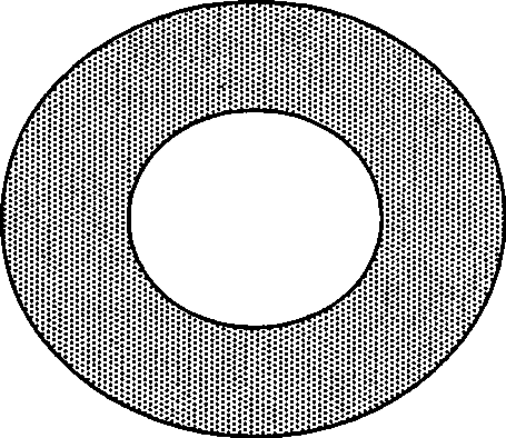
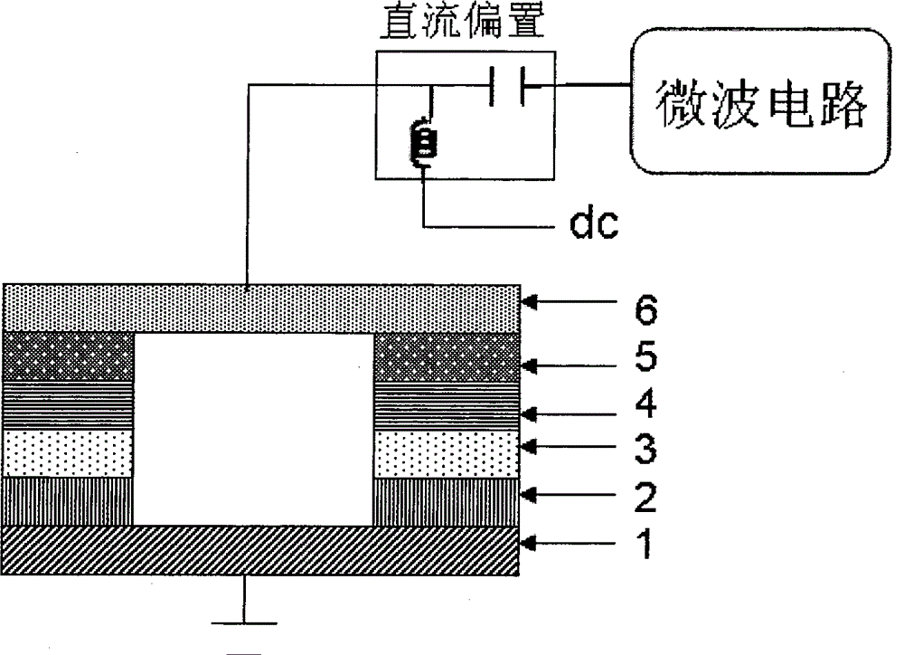
[0056] Figure 1-2 It is a schematic diagram of a spin microwave oscillator based on a non-pinning single-barrier circular magnetic multilayer film structure. From Figure 1-2 It can be seen that the spin microwave oscillator includes a non-pinning single-barrier annular magnetic multilayer film (such as Figure 1-1a ), DC bias (bias T) and microwave circuits. Wherein the DC bias includes a capacitor and an inductor, which are used to provide the DC current required for the work of the non-pinning type single-barrier annular magnetic multilayer film, and to pass the alternating signal; the microwave circuit includes an amplifier circuit, Filtering circuits and microwave antennas (not shown) are used to amplify and filter alternating signals and transmit microwave signals.
[0057] We use high-vacuum magnetron sputtering equipment under certain growth conditions, in the 1mm thick SrTiO cleaned by conventional methods 3 The lower buffer conductive layer Au with a thickness of...
Embodiment 2~4
[0062] The closed-shaped magnetic multilayer films of Examples 2-4 are obtained according to the method of Example 1 to obtain a spin microwave oscillator, and its working principle is the same as that described in Example 1. The closed magnetic multilayer films used in Examples 2-4 are listed in Table 1.
[0063] The closed magnetic multilayer film adopted in the embodiment 2-4 of table 1
[0064] Example Reference drawing number closed magnetic multilayer film 2 image 3 Pinned single-barrier annular magnetic multilayer film 3 Figure 5 Non-pinned Double Barrier Circular Magnetic Multilayers 4 Figure 6 Pinned Double Barrier Circular Magnetic Multilayers
Embodiment 5
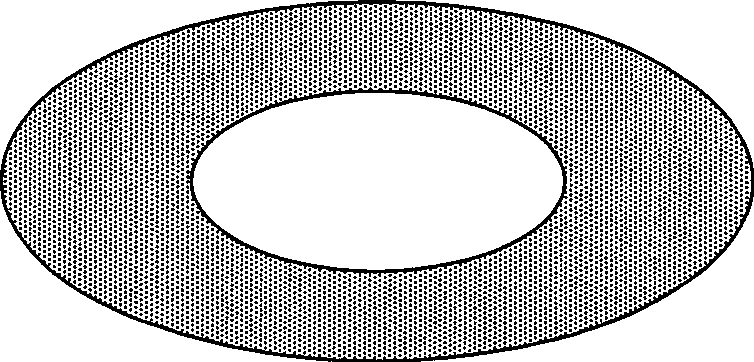
[0066] Figure 2-2 It is a schematic diagram of a spin microwave oscillator based on a non-pinning single-barrier circular magnetic multilayer film structure containing a metal core. The spin microwave oscillator includes a non-pinning single-barrier annular magnetic multilayer film containing a metal core, a DC bias, an external circuit dc2 and a microwave circuit, wherein the metal core is located in the geometry of the annular magnetic multilayer film central location (such as Figure 2-1a ). It should be noted that the shape of its cross section matches the shape of the magnetic multilayer film, that is, if the patterned shape of the magnetic multilayer film is an elliptical ring, the metal core is also elliptical (such as Figure 2-1b )
[0067] We use high-vacuum magnetron sputtering equipment under certain growth conditions, in the 1mm thick LaAlO cleaned by conventional methods 3 On the substrate, a lower buffer conductive layer Ru with a thickness of 30 nm, a hard...
PUM
 Abstract
Description
Claims
Application Information
 - R&D
- Intellectual Property
- Life Sciences
- Materials
- Tech Scout
- Unparalleled Data Quality
- Higher Quality Content
- 60% Fewer Hallucinations
Browse by: Latest US Patents, China's latest patents, Technical Efficacy Thesaurus, Application Domain, Technology Topic, Popular Technical Reports.
© 2025 PatSnap. All rights reserved.Legal|Privacy policy|Modern Slavery Act Transparency Statement|Sitemap|About US| Contact US: help@patsnap.com


