Method for obtaining high-purity sulphur from Claus reactive tail-gases

A Claus tail gas, Claus reaction technology, applied in separation methods, chemical instruments and methods, sulfur preparation/purification, etc., can solve the problems of insufficient hydrogen and large hydrogen sources, and reduce process design and process. steps, cost reduction, effect of reducing the amount of additional equipment

Inactive Publication Date: 2010-04-14
邵志辉
View PDF1 Cites 22 Cited by
  • Summary
  • Abstract
  • Description
  • Claims
  • Application Information

AI Technical Summary

Problems solved by technology

[0017] As can be seen from the above, traditional hydrogenation reduction refers to reducing all sulfides in the Claus reaction tail gas to hydrogen sulfide, and then processing through various channels to convert all sulfides into hydrogen sulfide, The required temperature is above 300 degrees, which cannot be met by medium-pressure steam, and an external heating furnace is required; in addition, the hydrogen source consumed is relatively large, and the hydrogen generated by the cracking in the combustion section cannot meet the requirements, so an external hydrogen source is required

Method used


Image

  • Method for obtaining high-purity sulphur from Claus reactive tail-gases
  • Method for obtaining high-purity sulphur from Claus reactive tail-gases
  • Method for obtaining high-purity sulphur from Claus reactive tail-gases

Examples


Embodiment 1

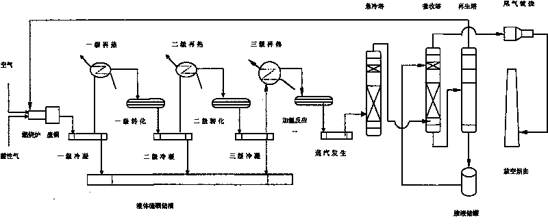
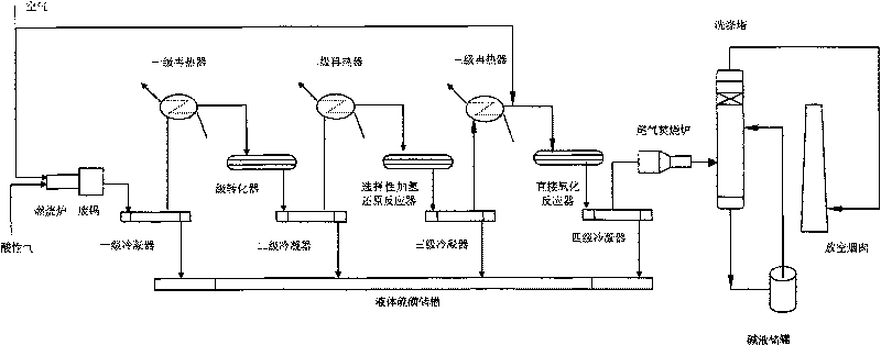
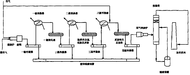
[0044] A method for obtaining high-purity sulfur from Claus reaction tail gas, comprising the following steps:

[0045] (1) Claus tail gas is preheated to 180℃~200℃ through heat exchange;

[0046] (2), the preheated gas enters the reduction reaction furnace filled with a selective reduction catalyst for the main reaction of 2H 2 +SO 2 =S+2H 2 The reduction reaction of O, wherein the selective reduction catalyst is the sulfur recovery catalyst of A999 from Shandong Schindler Chemical Group Co., Ltd.;

[0047] (3), the reacted process gas separates out liquid sulfur through the condenser;

[0048] (4) The process gas coming out of the condenser enters the adiabatic-isothermal integrated reactor filled with titanium-based catalysts for direct oxidation reaction after being re-allocated with oxygen and preheated;

[0049] (5) The gas coming out of the reactor passes through the sulfur condenser and separator to precipitate liquid sulfur, and the tail gas is incinerated, cooled...

Embodiment 2

[0051] The operating process of this embodiment is the same as that of Example 1, the difference being that in step (4) when the concentration of hydrogen sulfide in the process gas is below 1.2%, the oxidation reaction is carried out in an adiabatic reactor filled with a titanium-based catalyst .

Embodiment 3

[0053] The operation process of this embodiment is the same as that of Example 1, the difference being that in step (4) when the concentration of hydrogen sulfide in the process gas is below 1%, the oxidation reaction is carried out in an adiabatic reactor filled with a titanium-based catalyst .


PUM


Abstract

The invention relates to a method for obtaining high-purity sulphur from Claus reactive tail-gases, which belongs to the technical field of environmental protection. The method comprises steps as follows: (1) Claus tail-gas is preheated to reach the temperature between 160 DEG C to 300 DEG C; (2) the preheated gas enters a reduction reaction furnace filled with selective reaction catalysts to perform reduction reaction; (3) liquid sulphur is separated out of the reacted process gas via a condenser; (4) the process gas performs direct oxidization reaction inside a direct oxidizing reactor after being compensated with oxygen and preheated again; (5) liquid sulphur is separated out of gas on an outlet of the reactor via a sulphur condenser and a separator, tail gases after burned are cooled, washed by using an alkaline liquor and then discharged. The method overcomes the shortcoming that sulphur can not be produced by a traditional tail-gas hydrogenation reactor, improves total recovery efficiency of sulphur in a single process, and has the advantages of saving energy, lowering H2 consumption amount, reducing volume of absorption towers, decreasing arranged devices, lowering manufacturing cost and reducing operating load of the overall set of devices.

Description

technical field [0001] The invention belongs to the technical field of environmental protection, and in particular relates to a method for obtaining high-purity sulfur from Claus tail gas. Background technique [0002] Sulphides in crude oil or coal are converted to H during processing 2 S, and H 2 S is a highly toxic substance, which has a great poisonous effect on the human body and the environment. It must be treated in a harmless manner. The most suitable process is the sulfur recovery process. The acid gas in the refinery mainly comes from catalytic dry gas desulfurization, coking dry gas desulfurization, sewage gas stripping tower gas, hydrotreating unit desulfurization and other devices. [0003] The main processing flow of sour gas in refineries is: sulfur in crude oil → petroleum processing (atmospheric and vacuum) → gasoline\kerosene\diesel →hydrofining→H 2 S→sulfur recovery→sulfur; [0004] In a chemical plant using coal as raw material, the sour gas processin...

Claims


Application Information

Patent Timeline
Patent Type & Authority Applications(China)
IPC IPC(8): B01D53/48B01D53/76B01D53/86C01B17/04
CPCY02P20/10Y02P20/50
Inventor 邵志辉
Owner 邵志辉
Why Eureka
Try Eureka