
High-pressure powdered coal gasifier with back-heating system

A regenerative system and gasifier technology, which can be used in granular/powder fuel gasification, chemical industry, and the manufacture of combustible gas, etc., can solve problems such as the reduction of energy utilization efficiency, and achieve improved energy utilization efficiency and high gasification efficiency. , the effect of efficient use

Active Publication Date: 2013-01-02
SHANGHAI BOILER WORKS +1
View PDF0 Cites 0 Cited by
  • Summary
  • Abstract
  • Description
  • Claims
  • Application Information

AI Technical Summary

Problems solved by technology

Existing coal gasifier crude gas sensible heat recovery generally adopts radiant cooler plus convective cooler, or cold gas recirculation plus convective cooler. Both cooling methods use cooling water as the cooling medium, and the effective energy The loss is very huge, resulting in the subsequent reduction of energy utilization efficiency

Method used


Image

  • High-pressure powdered coal gasifier with back-heating system
  • High-pressure powdered coal gasifier with back-heating system

Examples


Embodiment 1

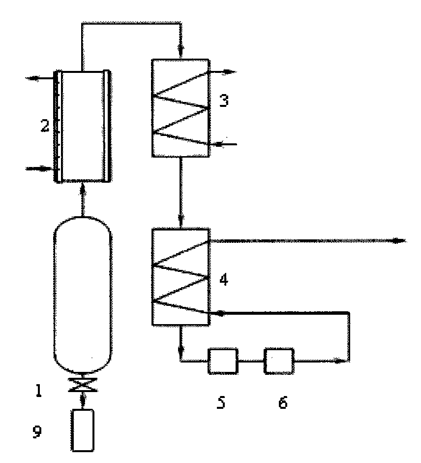
[0017] Such as figure 1 Shown is a schematic structural diagram of a high-pressure pulverized coal gasifier with a heat recovery system. The high-pressure pulverized coal gasifier consists of a water-cooled high-pressure pulverized coal gasification chamber 1 and a radiant crude gas cooler with a membrane water wall. 2. The first-stage heat recovery device 3, the second-stage heat recovery device 4, the dust collector 5, the desulfurization and denitrification purification equipment 6, and the slag removal equipment 9. The coal is composed of CO 2 Carry it into the water-cooled high-pressure pulverized coal gasification chamber 1, and react with the input gasification agent oxygen and water vapor to generate rich CO and H 2 The high-temperature crude gas and molten ash are discharged from the slagging equipment 9, and the high-temperature crude gas enters the radiant crude gas cooling device 2 equipped with a membrane water wall to cool below 900°C, and then enters the first-s...

Embodiment 2

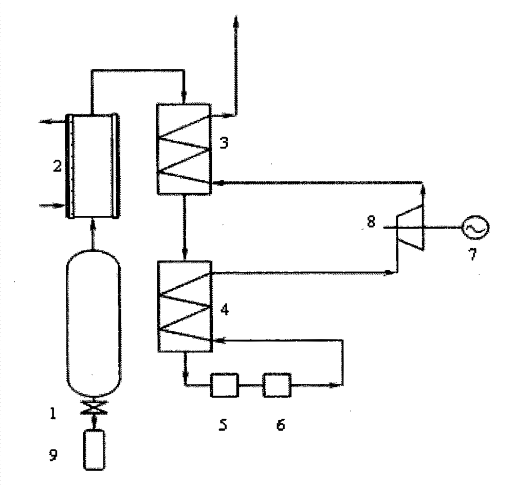
[0019] Such as figure 2 As shown, it is a structural schematic diagram of another high-pressure pulverized coal gasifier with a heat recovery system. The high-pressure pulverized coal gasifier is composed of a water-cooled high-pressure pulverized coal gasification chamber 1 and a radiant crude gas cooling system with a membrane water wall. 2, the first-stage heat recovery device 3, the second-stage heat recovery device 4, the dust collector 5, the desulfurization and denitrification purification equipment 6, the generator 7, the gas expansion turbine 8 and the slag removal equipment 9, and the coal is composed of CO 2 Carry it into the water-cooled high-pressure pulverized coal gasification chamber 1, and react with the input gasification agent oxygen and water vapor to generate rich CO and H 2 The high-temperature crude gas and molten ash are discharged from the slag discharge equipment 9 into the radiant crude gas cooling device 2 equipped with a membrane water wall to coo...


PUM


Abstract

The invention provides a high-pressure powdered coal gasifier with a back-heating system, which is characterized in that the gasifier comprises a water-cooling high-pressure powdered coal gasifying chamber; the water-cooling high-pressure powdered coal gasifying chamber is connected with a radiant type raw gas cooler with a membrane type water-cooling wall; the radiant type raw gas cooler with the membrane type water-cooling wall is connected with a cooled medium inlet of a first level back-heating device; a cooled medium outlet of the first level back-heating device is connected with a cooled medium inlet of a second level back-heating device; a cooled medium outlet of the second level back-heating device is connected with a dust collector; the dust collector is connected with desulfurization denitrification purification equipment; and the desulfurization denitrification purification equipment is connected with the cooled medium inlet of the second level back-heating device. The gasifier has the advantage of higher energy utilizing efficiency.

Description

technical field [0001] The invention relates to a high-pressure pulverized coal gasification furnace with a heat recovery system, belonging to the field of coal gasification equipment. Background technique [0002] In the 1980s, entrained-bed pressurized gasification technology rose internationally, showing excellent technical performance and environmental indicators, and thus became one of the world's recognized efficient and clean coal utilization technologies. The common characteristics of entrained bed gasification furnaces are: the gasification temperature is as high as 1300°C, the residence time of the reactants in the furnace is short, and satisfactory carbon conversion rate and gasification efficiency can be obtained, but the sensible heat taken away by the outlet gas increases. The thermal efficiency of the entrained bed is reduced. [0003] The current gasification technology has not been able to solve the problem of high-temperature sensible heat utilization of t...

Claims


Application Information

Patent Timeline
Patent Type & Authority Patents(China)
IPC IPC(8): C10J3/48C10J3/84
CPCY02E20/18Y02P20/10
Inventor 杨震曹子栋刘银河郭琴琴刘建斌张伯弟曹钧
Owner SHANGHAI BOILER WORKS
Learn More