
Reducing method for producing sponge iron by ultralow carbon emission

A sponge iron and ultra-low carbon technology, applied in the field of metallurgy, can solve the problems of carbon deposition and gas pollution, and achieve the effects of high metallization rate, high reduction efficiency and simplified layout

Inactive Publication Date: 2019-07-05
CISDI RES & DEV CO LTD
View PDF7 Cites 5 Cited by
  • Summary
  • Abstract
  • Description
  • Claims
  • Application Information

AI Technical Summary

Problems solved by technology

[0005] In view of the shortcomings of the prior art described above, the purpose of the present invention is to provide a reduction method for producing sponge iron with ultra-low carbon emissions, which is used to solve the problem of carbon precipitation and CO produced during the production of sponge iron in the prior art. 2 Gas pollution and other issues

Method used


Image

  • Reducing method for producing sponge iron by ultralow carbon emission
  • Reducing method for producing sponge iron by ultralow carbon emission
  • Reducing method for producing sponge iron by ultralow carbon emission

Examples


Embodiment 1

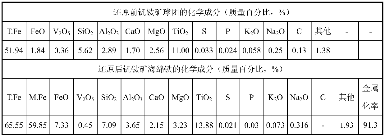
[0047] Production of vanadium-titanium ore sponge iron by reducing vanadium-titanium magnetite with this process

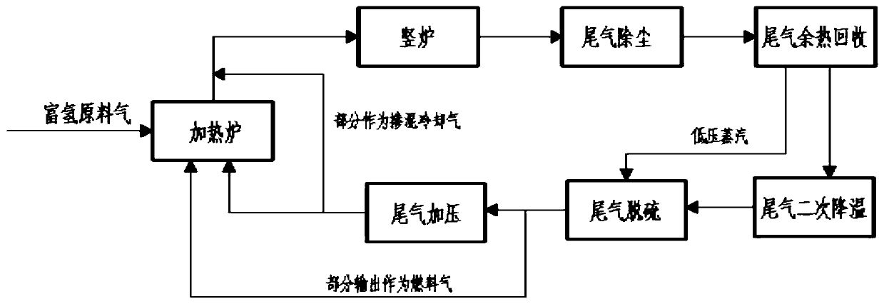
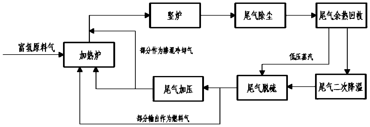
[0048] h 2 The volume ratio is 90%, N 2 The volume ratio is 2%, H 2 O The normal temperature hydrogen-rich raw material gas with a volume ratio of 8%, after purification, explosion limit determination and pressure regulation treatment, the raw material gas gauge pressure is 0.2MPa, and the tail gas discharged from the shaft furnace is dust-removed, waste heat recovery, secondary cooling, desulfurization Together with the pressurized furnace top exhaust gas, it enters the tubular heating furnace and is further raised to 980°C. The high-temperature exhaust gas discharged from the tubular heating furnace and part of the exhaust gas dust removal, waste heat recovery, secondary cooling, desulfurization and pressurized furnace roof After the tail gas is blended, the flow rate and preheating temperature of the blended cold air are controlled to form a reduced tail gas ...

Embodiment 2

[0053] Using this process to reduce common pellets to produce high-quality sponge iron

[0054] h 2 The volume ratio is 96%, N 2 The volume ratio is 2%, H 2 O The hydrogen-rich raw material gas at room temperature with a volume ratio of 2% has a gauge pressure of 0.25 MPa after purification, explosion limit determination and pressure adjustment treatment, and the exhaust gas discharged from the shaft furnace is dust-removed, waste heat recovered, secondary cooling, and desulfurization Together with the pressurized furnace top exhaust gas, it enters the tubular heating furnace for further temperature increase. The high-temperature exhaust gas discharged from the tubular heating furnace has a temperature of 930°C, and is then combined with part of the exhaust gas after dust removal, waste heat recovery, secondary cooling, desulfurization and pressurization. After the furnace top tail gas is blended, by controlling the flow rate of the blended cold air, a reduced tail gas with ...


PUM


Abstract

The invention provides a reducing method for producing sponge iron by ultralow carbon emission. The method comprises the following steps of feeding a hydrogen-rich raw material gas into a heating furnace, feeding into a vertical furnace after heating, and producing the sponge iron by using reduced iron ore. According to the reducing method, the furnace top tail gas discharged by the vertical furnace is fully recycled, the supplement amount of the hydrogen-rich raw material gas is saved, due to the arrangement of a heat pipe type heat exchanger, the heat exchange efficiency is high, the tail gas temperature is reduced, meanwhile, the tail gas waste heat is fully recycled in a way of by-producing low-pressure steam, and the energy consumption is saved; a wet desulfurization device is arranged, the desulfurization effect is good, low-pressure steam is fully utilized as a heat source required by itself, the furnace top tail gas is further purified, the erosion of H2S and other sulfide in the tail gas to the pipeline and device is reduced, and the service life of the device is prolonged.

Description

technical field [0001] The invention relates to the technical field of metallurgy, in particular to a reduction method for producing sponge iron with ultra-low carbon emissions. Background technique [0002] The direct reduction ironmaking process is an important link to realize the short process of iron and steel production, that is, the scrap steel / direct reduced iron-electric furnace process. Compared with the traditional blast furnace process, the direct reduction ironmaking process has the technical advantages of shorter process, no coking coal, and obvious energy saving and emission reduction effects. 2 It is an important development direction to improve the structure of steel products and improve the quality of steel products. [0003] The gas-based shaft furnace method is the mainstream direct reduction ironmaking technology in the world today. Currently, the direct reduced iron (ie, sponge iron) produced by this process accounts for more than 80% of the total outp...

Claims


Application Information

Patent Timeline
Patent Type & Authority Applications(China)
IPC IPC(8): C21B13/02C21C7/064
CPCC21B13/0073C21B13/02C21B2100/06C21C7/064
Inventor 吴开基张涛郭敏赵运建
Owner CISDI RES & DEV CO LTD
Learn More