
Composite guided wave structure formed by coupling metal nano lines, nano optical fiber and optical nano line

A technology of metal nanowires and nanofibers, applied in the direction of optical waveguide light guide, light guide, optics, etc., can solve the problems of unfavorable high-density integration, signal attenuation, heat generation, etc., and achieve easy control and adjustment, reduce device loss, and high coupling efficiency effect

Inactive Publication Date: 2010-05-05
ZHEJIANG UNIV
View PDF0 Cites 12 Cited by
  • Summary
  • Abstract
  • Description
  • Claims
  • Application Information

AI Technical Summary

Problems solved by technology

Metal nanowires have a smooth surface and a good crystal structure, which is a kind of surface plasmon waveguide that is easy to operate and integrate. However, the current coupling methods for exciting metal nanowires mainly include focusing coupling and prism coupling, which are not conducive to high-density integration. , and electromagnetic waves oscillating at optical frequencies inevitably have ohmic losses when they exist or transmit in metals, so devices made entirely of plasmonic waveguides face serious problems such as signal attenuation and heat generation, making them subject to practical applications restricted

Method used


Image

  • Composite guided wave structure formed by coupling metal nano lines, nano optical fiber and optical nano line
  • Composite guided wave structure formed by coupling metal nano lines, nano optical fiber and optical nano line
  • Composite guided wave structure formed by coupling metal nano lines, nano optical fiber and optical nano line

Examples


Embodiment Construction

[0011] The present invention will be further described below in conjunction with the accompanying drawings and embodiments, and the purpose and effect of the present invention will become more obvious.

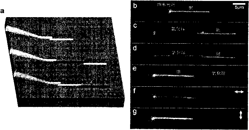
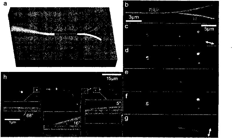
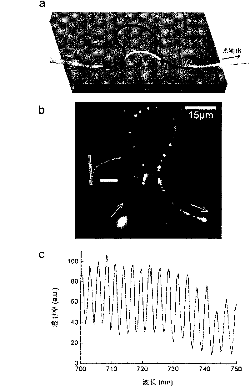
[0012] Such as figure 1 , 2 As shown, the present invention directly couples the nanofiber to the metal nanowire on the substrate to excite the surface plasmon resonance signal of the metal nanowire, or first couples the nanofiber to the optical nanowire and then passes the optical nanowire parallel or at a certain Angle-coupled excitation of metal nanowires. The signal output from the metal nanowire can be coupled out through the optical nanowire, and the output light has good polarization characteristics.

[0013] The diameters of the metal nanowires, nanofibers and optical nanowires are all 50-2000nm. In the composite structure, the coupling efficiency is determined by the overlapping length of the nanowires or the angle between the nanowires. The coupling angle varies ...


PUM

PropertyMeasurementUnit
diameteraaaaaaaaaa
diameteraaaaaaaaaa
diameteraaaaaaaaaa

Abstract

The invention discloses a composite guided wave structure formed by directly efficiently coupling metal nano lines, a nano optical fiber and an optical nano line. The nano optical fiber can be directly coupled with the metal nano lines, and the surface plasma resonance signals of the metal nano lines are excitated or collected by the near-field interaction of a subwavelength dimension. The metal nano lines can also be parallel to the optical nano line firstly by micro-nano operation or the metal nano lines contact with the optical nano line at a certain angle to form coupling, and then the tapered nano optical fiber is coupled with the nano lines. The composite guided wave mode has very high coupling efficiency and simple structure, the output light of the nano lines has very good polarization property, the coupling efficiency can be controlled by regulating the overlapping length of the nano lines of a coupling area or an angle between the nano lines, the simultaneous coupling and excitation of one optical nano line to a plurality of metal nano lines can be realized, a coupler, a beam splitter, a Mach-Zehnder interferometer and an annular resonant cavity component which have a composite structure can be realized, and the composite guided wave mode can be compatible to the traditional optical fiber system.

Description

technical field [0001] The invention relates to a micro-nano optical structure, in particular to a composite waveguide structure composed of metal nanowires, nanofibers and optical nanowires coupled with high efficiency. Background technique [0002] With the increasing requirements for high-capacity and high-speed optical information transmission and processing such as optical communication and optical computing, the characteristic size of photonic devices and their interconnected optical circuits is moving towards the sub-wavelength and nanometer scale, and surface plasmons with the ability to break through the diffraction limit of light Bulk polaritons show potential applications in nanoscale optical information carriers. Metal nanowires have a smooth surface and a good crystal structure, which is a kind of surface plasmon waveguide that is easy to operate and integrate. However, the current coupling methods for exciting metal nanowires mainly include focusing coupling an...

Claims


Application Information

Patent Timeline
Patent Type & Authority Applications(China)
IPC IPC(8): G02B6/122G02B6/10
Inventor 童利民郭欣杨青张奚宁马耀光虞华康
Owner ZHEJIANG UNIV
Learn More