
Catalyst coated membrane electrode of fuel cell with self-moistening function and preparation method thereof

A technology of catalyst coating and catalyst layer, which is applied in the direction of fuel cells, battery electrodes, fuel cell parts, etc., can solve the problems of increased manufacturing process and cost of membrane electrode assemblies, and achieves easy mass production, uniform thickness, enhanced The effect of water retention capacity

Active Publication Date: 2012-01-11
SUNRISE POWER CO LTD
View PDF4 Cites 0 Cited by
  • Summary
  • Abstract
  • Description
  • Claims
  • Application Information

AI Technical Summary

Problems solved by technology

In the measures of the prior art, a waterproof layer or a water-retaining layer is added between the catalyst layer and the gas diffusion layer of the membrane electrode assembly, which increases the manufacturing process of the membrane electrode assembly and increases the cost.

Method used


Image

  • Catalyst coated membrane electrode of fuel cell with self-moistening function and preparation method thereof
  • Catalyst coated membrane electrode of fuel cell with self-moistening function and preparation method thereof

Examples


Embodiment 1

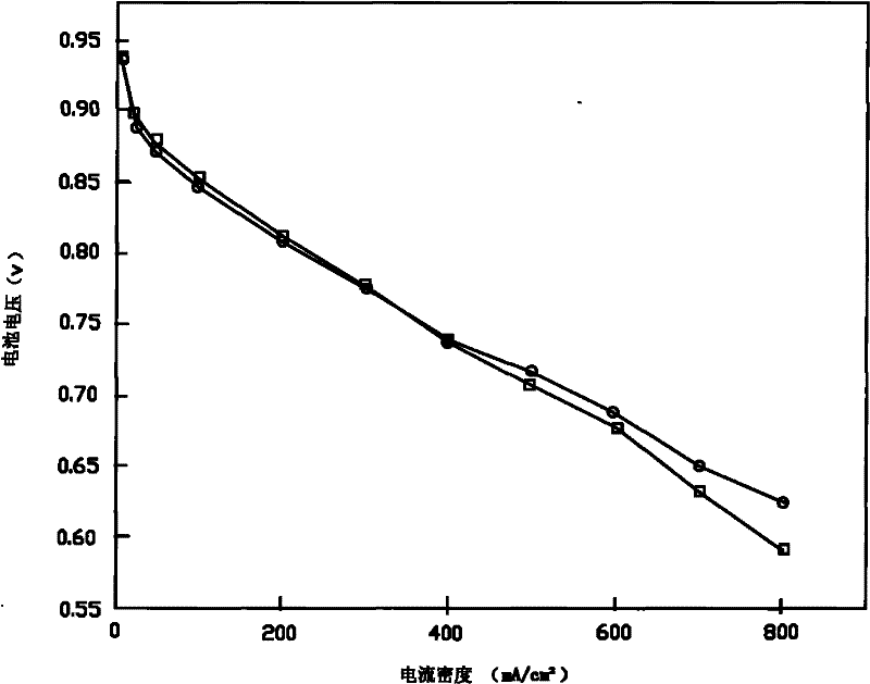
[0019] 1) Preparation of inner catalyst layer electrode slurry. Weigh 21 mg of 50% wt.Pt / C catalyst, 210 mg of 5% Nafion solution, 10.5 mg of lithium carbonate, and 3.2 mg of fumed silica into a weighing bottle, and drop 5 drops of deionized water into the catalyst with a rubber dropper. Wet well, then add 5g of isopropanol. Place the weighing bottle in an ultrasonic generator and ultrasonically stir for 30 minutes, and set aside.

[0020] 2) Preparation of the electrode slurry for the outer catalyst layer. Weigh 21 mg of 50% wt.Pt / C catalyst, 140 mg of 5% Nafion solution, 10.5 mg of lithium carbonate, and 2 mg of fumed silica into a weighing bottle, and drop 5 drops of deionized water into the catalyst to fully Wet, and add 5 g of isopropanol. Place the weighing bottle in an ultrasonic generator and ultrasonically stir for 30 minutes, and set aside.

[0021]3) The effective spraying area is 34.3cm 2 The NRE211 film (6×14 cm in size) was fixed on the vacuum hot stage of t...

Embodiment 2

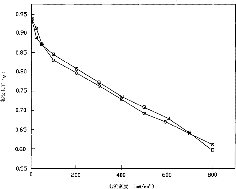
[0028] 1) Weigh 85 mg of Pt black catalyst, 850 mg of 5% Nafion solution, 42 mg of ammonium oxalate and 128 mg of 10% silica hydrosol into a weighing bottle, and then add 20 g of isopropanol. Place the weighing bottle in an ultrasonic generator and ultrasonically stir for 30 minutes, and set aside.

[0029] 2) Weigh 170 mg of 50% Pt / C catalyst, 1133 mg of 5% Nafion solution, 85 mg of ammonium oxalate and 170 mg of 10% silica hydrosol into a weighing bottle, and then add 40 g of isopropanol. Place the two weighing bottles in an ultrasonic generator and ultrasonically stir for 30 minutes, and set aside.

[0030] 3) Set the effective area to 283cm 2 The composite film (with a size of 10.1×41.2 cm) was fixed on the vacuum hot stage of the spraying machine, and the temperature of the hot stage was 140°C.

[0031] 4) Connect the electrode slurry prepared in step 1) to the pump, and connect the pump to the ultrasonic nozzle. Turn on the equipment and spray according to the program...


PUM


Abstract

The invention provides a catalyst coated membrane electrode of a proton exchange membrane fuel cell with self-moistening function, which is characterized in that catalyst coatings on two side surfaces of a proton exchange membrane are provided with an inner catalyst layer and an outer catalyst layer, the catalyst coating close to the proton exchange membrane is the inner catalyst layer, the content of a self-moistening agent and proton exchange membrane resin in the inner catalyst layer is high, and the catalyst coating close to a gas dispersion layer is the outer catalyst layer, the content of the self-moistening agent and the proton exchange resin in the outer catalyst layer is low, and Pt loadings of the inner catalyst layer and the outer catalyst layer are same. The invention strengthens the moisture holding capacity of the electrode by adding the self-moistening agent in electrode slurry, enables a membrane electrode assembly to have stable electric output in a low-moistening or no-moistening fuel or oxidant environment, and has simple structure as the catalyst coated membrane electrode with self-moistening function is prepared by adopting a machine spraying technology, uniform thickness of the catalyst coating, good repeatability and easy batch production.

Description

technical field [0001] The invention relates to the field of proton exchange membrane fuel cells, in particular to a catalyst-coated membrane-electrode assembly for a proton-exchange membrane fuel cell, in particular to a catalyst-coated membrane-electrode assembly with a self-humidification function. Background technique [0002] Catalyst-coated membrane electrode (CCM), because the catalyst layer can be developed to be ultra-thin (thickness <5 μm), the utilization rate of the catalyst is improved, and the interfacial mass transfer resistance between the catalyst layer and the proton exchange membrane is reduced, which is conducive to improving battery efficiency. . At the same time, the catalyst-coated membrane electrode is conducive to the functional differentiation of fuel cell components, which facilitates the post-treatment of the electrode catalyst layer and endows it with more functions. Therefore, the application of catalyst-coated membrane electrodes has become...

Claims


Application Information

Patent Timeline
Patent Type & Authority Patents(China)
IPC IPC(8): H01M8/02H01M4/88H01M8/04828
CPCY02E60/50Y02P70/50
Inventor 张可侯中军邢丹敏宋书范张玉海
Owner SUNRISE POWER CO LTD
Learn More