
Single preheating, sintering, igniting and heat insulating furnace

A technology for ignition and holding furnaces and preheating furnaces, which is applied in the direction of furnaces, furnace types, and combustion methods. It can solve problems such as the difficulty of having a clean heat source for the ignition furnace, no products put into use, and the impact on the strength of sintered ore, and achieves a significant energy-saving effect. , improve the ambient temperature, the effect of compact structure

Active Publication Date: 2010-06-09
常州市黑山烧结点火炉制造有限公司
View PDF1 Cites 13 Cited by
  • Summary
  • Abstract
  • Description
  • Claims
  • Application Information

AI Technical Summary

Problems solved by technology

[0003] Chinese patent announcement number CN2708125 discloses a regenerative sintering machine ignition furnace with low calorific value gas. Since it is difficult to have a clean heat source in the ignition furnace, no product has been put into use in China so far.
However, the self-preheating gas ignition holding furnace has a poor preheating effect, which has a quenching effect on the sintered ore after ignition and affects the strength of the sintered ore.
If the form of double preheating is adopted, the structure is complicated and the cost is high. When preheating the blast furnace gas, heat exchange damage is easy to occur, so there is a big safety hazard.

Method used


Image

  • Single preheating, sintering, igniting and heat insulating furnace
  • Single preheating, sintering, igniting and heat insulating furnace
  • Single preheating, sintering, igniting and heat insulating furnace

Examples


Embodiment Construction

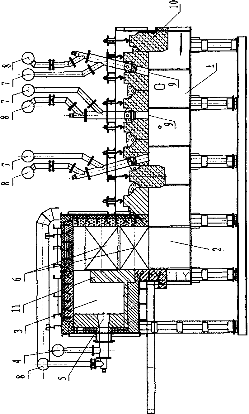
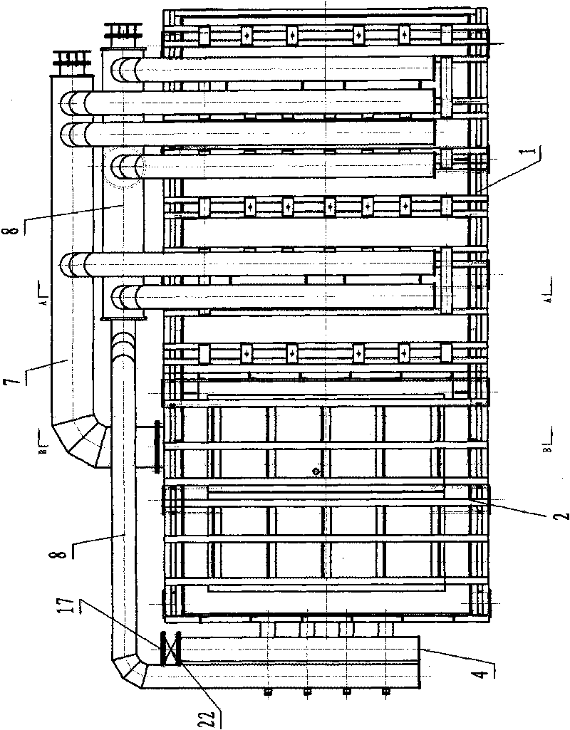
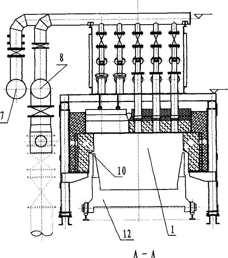
[0016] See Figure 1-5 , the single preheating sintering ignition and holding furnace of this embodiment includes: ignition section 1 and insulation section 2, ignition section 1 and insulation section 2 are integrated with each other, and are arranged on the upper part of sintering machine trolley 12; insulation section 2 includes air preheating Furnace 3, the air preheating furnace 3 is provided with an air heat exchanger 6; the ignition section 1 includes a plurality of burners 9, and each burner 9 is connected with the blast furnace gas pipe 8 and the hot air pipe 7; the air heat exchanger 6 The cold air inlet 4 is connected with the cold air input pipe 4, and the cold air input pipe 4 is provided with a fan 21; the hot air outlet of the air heat exchanger 6 is connected with the inlet of the hot air pipe 7; the air heat exchanger 6 is arranged above the trolley 12, and during operation, the exhaust gas output from the air preheating furnace 3 keeps the sintering mixture o...


PUM


Abstract

The invention relates to a single preheating, sintering, igniting and heat insulating furnace with the advantages of simple structure, little pollution, obvious energy saving effect and high safety. The furnace comprises an igniting section and a heat insulating section, wherein the igniting section and the heat insulating section are connected into a whole and are arranged on a sintering machine table. The heat insulating section comprises an air preheating furnace, and an air heat exchanger is arranged in the air preheating furnace. The igniting section comprises a plurality of burning nozzles, and each burning nozzle is connected with a blast furnace gas pipe and a hot air pipe. A cold air inlet and a cold air input tube of the air heat exchanger are connected, and a fan is arranged on the cold air input tube. A hot air outlet of the air heat exchanger is connected with an inlet of the hot air tube. The air heat exchanger is arranged on a trolley. When the single preheating, sintering, igniting and heat insulating furnace is in working, the sintering compound of the waste gas trolley outputted by the air preheating furnace is insulated, and sucked into a large fume passage by the sintering compound surface of the trolley. The large fume passage is connected with the hot waste gas heat energy recovery system and the waste gas treating system to recover and utilize heat energy and remove harmful elements of sulphur and the like in the waste gas.

Description

technical field [0001] The invention relates to a hot sintering machine sintering ignition furnace in the metallurgical industry, in particular to a single preheating sintering ignition and heat preservation furnace. Background technique [0002] Sintering is an important part of the metallurgical industry, especially the ore preparation process in iron and steel smelting, and it is also one of the key operations that affects the energy consumption indicators of the entire smelting process. At present, most sintering plant ignition furnaces use low calorific value gas (usually blast furnace gas) as fuel. Due to the low calorific value of low calorific value gas, the gas or air must be preheated to meet the ignition temperature required by the sintering process. A preheating furnace must be built to preheat gas and air, resulting in a large shape of the ignition furnace, high investment and many safety hazards. In addition, the waste gas generated when the preheating furnace...

Claims


Application Information

Patent Timeline
Patent Type & Authority Applications(China)
IPC IPC(8): F27B21/08F23L15/00
CPCY02E20/34
Inventor 孙小平
Owner 常州市黑山烧结点火炉制造有限公司
Learn More