Phase-change temperature testing system

A technology of testing system and phase change temperature, applied in the investigation stage/state change, etc., can solve the problems of measurement inaccuracy, light transmittance change, application range limitation, etc., achieve intuitive and reliable results, avoid measurement errors, and test reliable high degree of effect

Active Publication Date: 2010-06-09
WUHAN SCHWAB INSTR TECH
View PDF11 Cites 21 Cited by
  • Summary
  • Abstract
  • Description
  • Claims
  • Application Information

AI Technical Summary

Problems solved by technology

[0004] The commonly used means of measuring the phase transition temperature of materials mainly include differential thermal analyzer (DSC) and variable temperature XRD, among which the former belongs to destructive measurement, and the thin film sample must be scraped into powder, which will inevitably destroy the film layer structure, resulting in measurement errors. Inaccurate. In addition, due to the limitation of its sensitivity, the sample mass is generally required to be greater than a few milligrams, and thin film samples cannot be measured at all; while the measurement accuracy of variable temperature XRD is limited, and the thermal expansion of the crystal at high temperature will cause large errors.
The phase change temperature test device shown in the Chinese invention patent "Phase Change Temperature Test Device" (publication number CN1253286, publication date 2000.05.17) can only be used to measure samples with better light transmission, and most thin film materials especially The light transmittance of thin film phase change materials is very low, and its light transmittance changes sharply with the change of film thickness, which greatly limits its application range

Method used


Image

  • Phase-change temperature testing system
  • Phase-change temperature testing system
  • Phase-change temperature testing system

Examples


Embodiment Construction

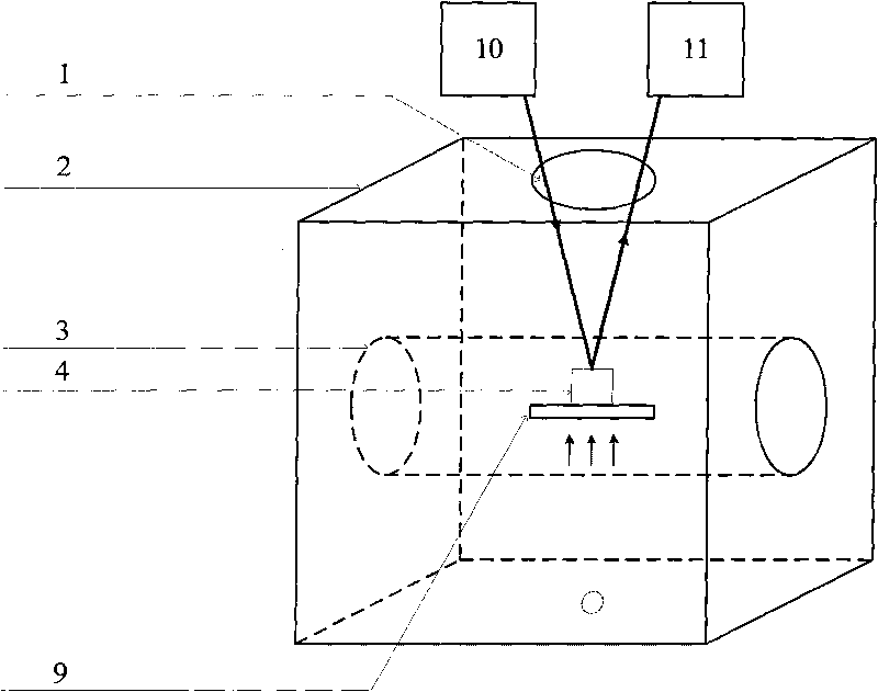
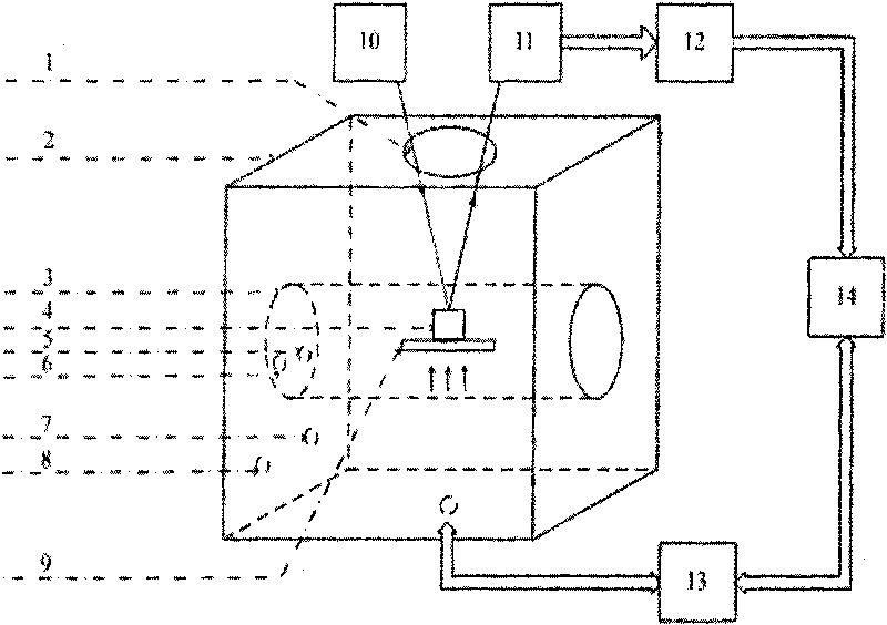
[0022] The working principle of this system is: the optical properties of thin film materials will have a large difference before and after the phase change. Taking the chalcogenide phase change material as an example, its crystalline state is an ordered state and has a large reflectivity to light; the amorphous state In a disordered state, the reflectivity of light is small, and the difference can be as high as 80%. During the test, the sample to be tested is heated in the vacuum heating furnace according to the set heating rate, a beam of constant power laser light is incident on the surface of the sample and reflected, the reflected light power is detected by the photodetector, the reflected light power and the actual incident light power The ratio of is the reflectance of the sample at a certain temperature point, from which the change of the reflectance of the sample with temperature can be obtained. After the corresponding temperature value and sample reflectance are col...


PUM

PropertyMeasurementUnit
wavelengthaaaaaaaaaa
crystallization temperatureaaaaaaaaaa

Abstract

The invention discloses a phase-change temperature testing system, which has the following structure that: a light-through hole is reserved on a cover plate of a heating furnace in which a furnace chamber is arranged; a sample holder is positioned in the furnace chamber and is positioned under the light-through hole; a laser and a photoelectric detector are arranged above the light-through hole; and the photoelectric detector is positioned on a light path of a sample to be tested for reflecting laser beams. The phase-change temperature testing system can be additionally provided with a signal amplification and acquisition circuit, a temperature control sensing circuit and a data processor. The system has relatively higher testing sensitivity, can test the phase-change temperature of a thin film thinner than 1 nm, directly test the phase-change temperature of a thin film sample without damage to the sample and obtain more material thermodynamic parameters through temperature-change measurement at different heating rates, and has the characteristics of simple operation, low cost and relatively higher testing reliability.

Description

technical field [0001] The invention belongs to the thin film performance testing technology, and in particular relates to a test system for the phase transition temperature of thin film materials. The system can measure the crystallization temperature of the thin film material, the phase transition temperature and the melting temperature between different structural phases in the crystal state. Background technique [0002] At present, phase change materials mainly based on chalcogenides are widely used in information storage, energy storage, sensors, logic devices, artificial neural networks and other fields. Taking phase change memory (PCRAM) as an example, it uses the thermal effect of electric pulses to reversibly change phase change materials (mainly chalcogenide compounds) between crystalline and amorphous states, and the huge resistance value of the material in the two states The difference is to store data, in which the crystalline state is a low-resistance state, a...

Claims


Application Information

Patent Timeline
Patent Type & Authority Applications(China)
IPC IPC(8): G01N25/02G01N25/12
Inventor 缪向水童浩程晓敏
Owner WUHAN SCHWAB INSTR TECH
Why Eureka
Try Eureka