

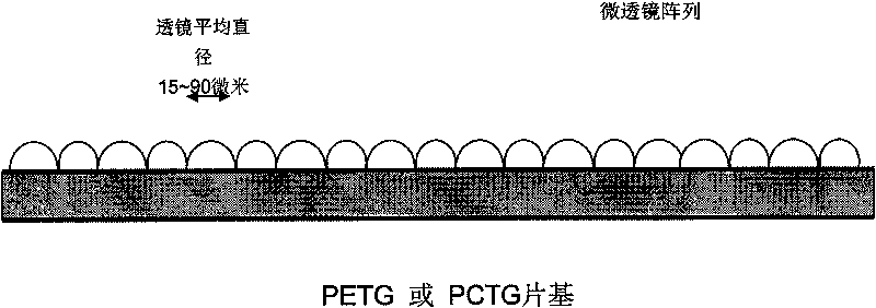
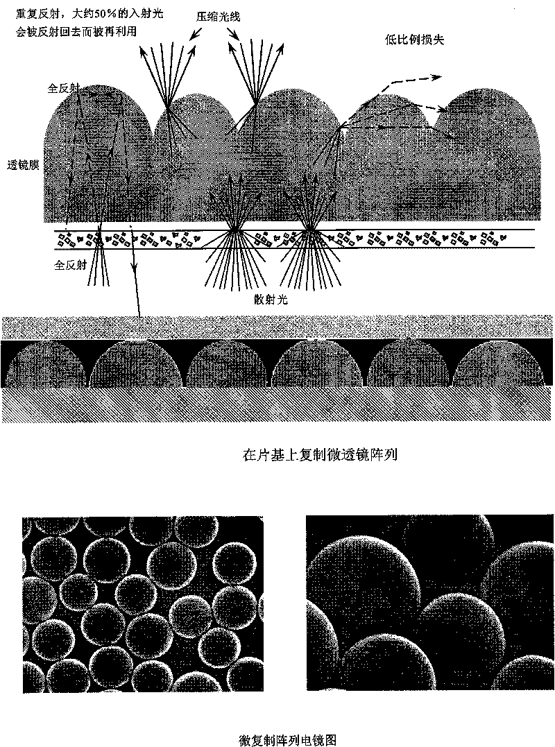
Duplicated array brightness enhancement film of large-viewing angle micro lens
A micro-replication and micro-lens technology, applied in the fields of lenses, optics, instruments, etc., can solve the problems of unfavorable large-scale promotion, poor optical gain performance, and high manufacturing process requirements
- Summary
- Abstract
- Description
- Claims
- Application Information
AI Technical Summary
Problems solved by technology
Method used
Image


Examples
Embodiment 1
[0017] [Example 1] Select a 35CrMo seamless steel pipe with a diameter greater than 200 mm. After correcting the dynamic balance, the two ends are equipped with shaft heads to make a hollow shaft, and then the circumferential surface of the hollow shaft is ground on a grinding machine until the surface is rough. The degree Ra0.2 microns, forming a mirror-like circumferential body. Choose a wire mesh whose mesh is slightly smaller than the diameter of the model to be replicated, and PMMA or PS particle balls whose diameter matches the nominal diameter of the model. Other types of organic material particle balls can also be used, and the particle balls can be uniformly adsorbed by electrostatic adsorption. Adsorbed on the surface of the mirror surface, the microspherical particles are tightly wrapped with wire mesh and attached to the cylindrical surface, axially pressed against each other to eliminate the gap between particles, and the number of particles in the wire mesh coatin...
Embodiment 2
[0018] [Example 2] Choose a 0.1mm stainless steel plate, spread the cast particles evenly on the surface of the plate, then cover it with a polyester mesh, press it tightly so that the beads are close to the steel plate, and then soak in the nickel In the phosphorus solution, stop the reaction when the theoretical coating thickness reaches half of the particle diameter. After taking it out, refer to the first method to clean up the remaining particles. The stainless steel plate is crimped and attached to the circular shaft to make a microlens array replication mold.
Embodiment 3
[0019] [Example 3] Mix the molded particles into epoxy resin or other high-strength resins, the particle distribution density is controlled according to calculation, and then the resin is evenly coated on the metal round shaft. The size of D+h / 2 is turned, the remaining particles are taken out, and then electroless metal is plated, and the replica mold is completed.
PUM
 Abstract
Description
Claims
Application Information