Heat and cool power cogeneration system of integrated multi-functional efficient mini-type gas turbine

A technology of micro gas turbine and cogeneration of cooling, heating and power, which is applied in the direction of gas turbine devices, machines using waste heat, mechanical equipment, etc., can solve the problems of power generation and power generation efficiency decline, insufficient use of flue gas, waste of flue gas, etc., to achieve Improve the power and efficiency of power generation, improve the cooling capacity of the system, and improve the effect of power generation efficiency

Inactive Publication Date: 2010-06-30
NORTH CHINA ELECTRIC POWER UNIV (BAODING)
View PDF0 Cites 31 Cited by
  • Summary
  • Abstract
  • Description
  • Claims
  • Application Information

AI Technical Summary

Problems solved by technology

This is because the cooling, heating and power loads of the cogeneration system are constantly changing in practical applications, and the load demand for cooling, heating and power cannot be guaranteed to match at all times, so the advantages of cascade utilization of energy in the cogeneration system cannot be fully utilized
The load demand mismatch of electric cooling and heating has the following situations: when the micro gas turbine cooling, heating and power cogeneration system has no cooling and heating demand, the cogeneration system will be in the state of pure power generation, and the flue gas is completely wasted; when the micro gas turbine cooling and heating When the power demand of the cogeneration system is high and the cooling and heating demand is low, the flue gas after power generation is not fully utilized; in summer high temperature weather, because the micro gas turbine is a volumetric device, its power generation and power generation efficiency will drop significantly, and the cogeneration The waste heat cooling power of the system will also decrease, but at this time, the electrical load and cooling load of the system are in a state of increase, and there is a contradiction between the demand of the system and the working state of the micro-gas turbine, etc.

Method used


Image

  • Heat and cool power cogeneration system of integrated multi-functional efficient mini-type gas turbine
  • Heat and cool power cogeneration system of integrated multi-functional efficient mini-type gas turbine

Examples


Embodiment 1

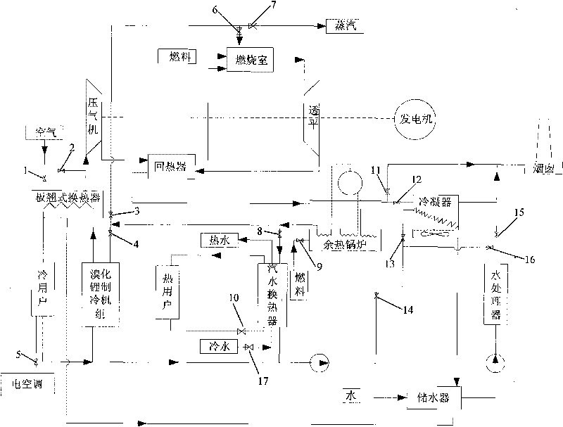
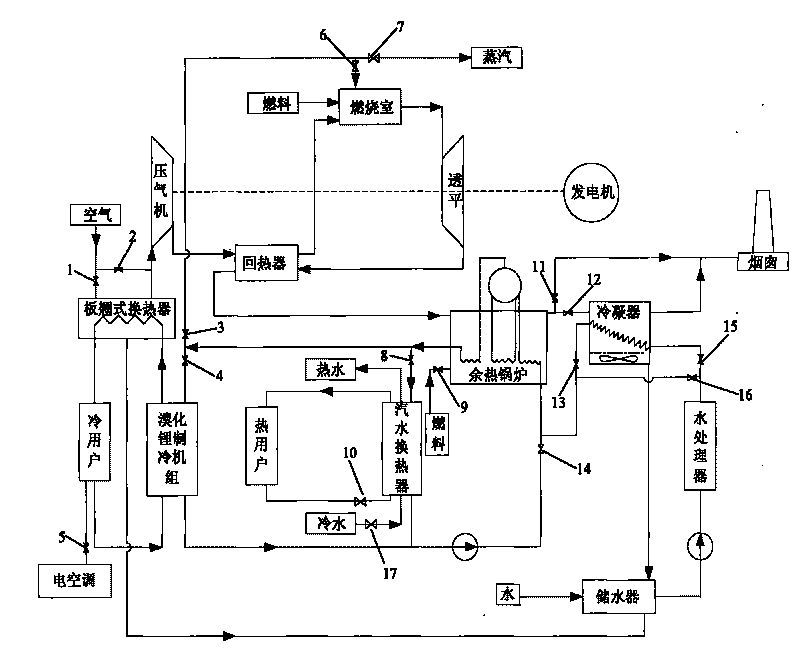
[0027] Typical winter heating working mode: the second valve 2, the eighth valve 8, the tenth valve 10, the eleventh valve 11, and the fourteenth valve 14 are opened, the ninth valve 9 is opened or closed according to the heat load, and other valves are closed . The air directly enters the compressor for compression, and then enters the combustion chamber after being heated by the flue gas in the regenerator. The gas generated by the combustion of air and fuel in the combustion chamber enters the turbine to expand and do work. The air is heated in the boiler, then enters the waste heat boiler to produce steam, and finally the flue gas is directly discharged from the chimney. The steam enters the steam-water heat exchanger to produce hot water for heating, and the steam condensed water returns to the waste heat boiler as make-up water. If additional make-up water is needed, the sixteenth valve 16 can be opened to make up water from the water storage.

Embodiment 2

[0029]Typical summer cooling working mode: the first valve 1, the fourth valve 4, the fifth valve 5, the eleventh valve 11, and the fourteenth valve 14 are opened, the ninth valve 9 is opened or closed according to the cooling load, the other valves are closure. The air first enters the plate warp heat exchanger and is cooled, then enters the compressor for compression, and then enters the combustion chamber after being heated by the flue gas in the regenerator, and the gas produced by the combustion of air and fuel in the combustion chamber enters the turbine for expansion. The flue gas from the turbine outlet first heats the air in the regenerator, then enters the waste heat boiler to produce steam, and finally the flue gas is discharged from the chimney. After the gas expands in the turbine, the air is heated in the regenerator, and then enters the waste heat boiler to produce steam, and finally the flue gas is directly discharged from the chimney. The steam produced by th...

Embodiment 3

[0031] Typical working mode without cooling and heating load (reinjection steam power generation mode): the second valve 2, the third valve 3, the sixth valve 6, the twelfth valve 12, the thirteenth valve 13, and the fifteenth valve 15 are opened, The other valves are closed. The air directly enters the compressor for compression, and then enters the combustion chamber after being heated by the flue gas in the regenerator. The gas generated by the combustion of air and fuel in the combustion chamber enters the turbine to expand and do work. The air is heated in the boiler, then enters the waste heat boiler to produce steam, and finally the flue gas is discharged from the chimney after dewatering by the condenser. The steam produced by the waste heat boiler is re-injected into the combustion chamber and burned together with fuel and air, increasing the amount of gas and thus increasing the work of the turbine. As the steam is reinjected into the combustion chamber, the flue ga...


PUM


Abstract

The invention proposes a heat and cool power cogeneration system of an integrated multi-functional efficient mini-type gas turbine, which belongs to the novel heat and cool power cogeneration system device. To solve the frequent mismatching of cold and heat load and low efficiency operation of the conventional cogeneration system, measures such as steam reinjection, inlet gas cooling, gas fume and condensate water recovery are introduced on the basis of the heat and cool power cogeneration system of the mini-type gas turbine; in addition, the number of steam outlets and hot-water outlets is increased, thus forming the heat and cool power cogeneration system of the integrated multi-functional efficient mini-type gas turbine. The system is provided with various operation modes suitable for different occasions, can effectively solve the problem of mismatching of cold and heat load of the cogeneration system, so that the system can keep working in highly efficient mode.

Description

technical field [0001] The invention belongs to cooling, heating and power cogeneration equipment, in particular to an integrated multifunctional and high-efficiency micro gas turbine cooling, heating and power cogeneration system. Background technique [0002] Micro gas turbine cogeneration system is one of the main forms of distributed energy with promising prospects. Theoretically, the combined cooling, heating and power generation system of micro gas turbines can realize cascade utilization of energy, and the comprehensive utilization efficiency of energy can reach more than 80%. However, a large number of projects have proved that it is relatively successful that the comprehensive utilization efficiency can reach 60%. This is because the cooling, heating and power load of the cogeneration system is constantly changing in practical applications, and the load demand for cooling, heating and power cannot be guaranteed to match at all times, so the advantages of cascade ut...

Claims


Application Information

Patent Timeline
Patent Type & Authority Applications(China)
IPC IPC(8): F02C6/18F25B27/02
CPCY02E20/14Y02A30/274
Inventor 段立强杨勇平和彬彬徐钢
Owner NORTH CHINA ELECTRIC POWER UNIV (BAODING)
Why Eureka
Try Eureka